Flat plate heat pipe and manufacturing method thereof

A flat plate heat pipe and a manufacturing method technology, which are applied in the field of heat transfer and heat dissipation, can solve problems such as affecting the internal overall gas-liquid circulation efficiency, the overall performance of the flat plate heat pipe, and the inability to meet heat dissipation, so as to avoid slowing down the condensation speed and avoid working fluids. The effect of poor reflow and avoiding the increase of heat transfer resistance

Active Publication Date: 2016-11-09
GUANGDONG UNIV OF TECH
View PDF5 Cites 29 Cited by
  • Summary
  • Abstract
  • Description
  • Claims
  • Application Information

AI Technical Summary

Problems solved by technology

[0004] However, due to the existence of the liquid-absorbing core of the flat heat pipe, part of the condensed liquid cannot return immediately and adheres to the condensation cover, so that the condensation of the steam becomes film-like condensation. When the steam exchanges heat with the condensation cover, it needs to pass through the liquid film, resulting in The thermal resistance increases and the condensation speed slows down, which affects the overall internal gas-liquid circulation efficiency and reduces the heat dissipation performance; when the liquid drawn back by the liquid-absorbing core cannot meet the amount required for evaporation, the liquid-absorbing core at the evaporating end dries up, and the evaporation end The temperature of the wall surface rises sharply, causing the wall surface of the evaporation end to burn out
In addition, due to the relatively large heat exchange area of ​​the flat heat pipe, in order to ensure its mechanical strength and reduce its deformation after heating, it is usually necessary to add support columns, and this measure is likely to cause the support columns to be deformed by heat, dislocation, instability, and poor flow of working fluid. and other problems, resulting in a serious decline in the overall performance of the flat heat pipe, which cannot meet the heat dissipation requirements

Method used


Image

  • Flat plate heat pipe and manufacturing method thereof
  • Flat plate heat pipe and manufacturing method thereof
  • Flat plate heat pipe and manufacturing method thereof

Examples


preparation example Construction

[0075] The present application preferably carries out the preparation of hydrophobic thin layer, and the preparation process of described hydrophobic thin layer is specifically:

[0076] Place the copper powder on the position of the condensing cover except the boss, heat and oxidize, add silver nitrate solution to the oxidized copper powder, add n-dodecyl mercaptan to the condensing cover, and then clean the condensing cover After the surface of the board is heated, dried and pressed, a condensation cover board with a thin hydrophobic layer of copper-based microstructure is obtained.

[0077] In the present application, it is preferred to prepare the liquid filling pipe at the end. The preparation of the liquid filling pipe is a technical means well known to those skilled in the art, and there is no special limitation here. The liquid filling tube is arranged in the through hole. The manufacturing process of the through holes is not particularly limited in the present applic...

Embodiment 2

[0083] The structure of the flat heat pipe of this embodiment is the same as that of Embodiment 1. As a preferred solution, this embodiment has been improved as follows:

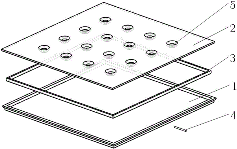
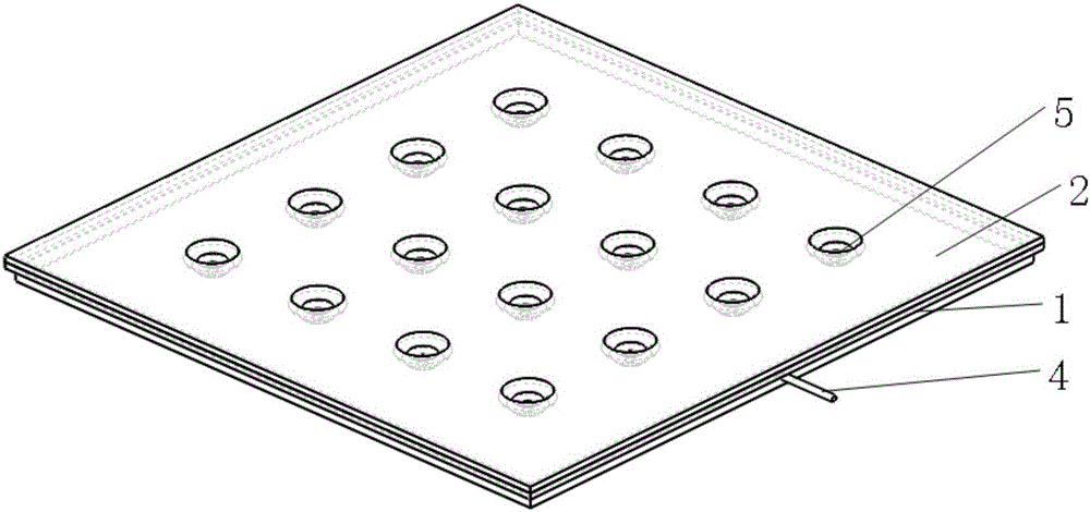
[0084] The evaporation cover plate 1 is used as the evaporation surface of the flat heat pipe, and its inner bottom surface is covered with a thin layer of hydrophilic copper hydroxide microstructure, and the hydrophilic copper hydroxide microstructure thin layer is put into the surface by the evaporation cover plate 1 Potassium hydroxide solution is used as an anode for electrochemical dissolution, and the hydrophilic copper hydroxide microstructure thin layer has a hydrophilicity with a contact angle of less than 10°; the inner bottom surface of the condensation cover plate 2 is covered with a hydrophobic copper base The microstructure thin layer, the hydrophobic copper-based microstructure thin layer is synthesized by reacting oxidized copper powder, silver nitrate solution and n-dodecyl mercaptan on the con...

Embodiment 3

[0086] The structure of the flat heat pipe of this embodiment is the same as that of Embodiment 1. As a preferred solution, this embodiment has been improved as follows:

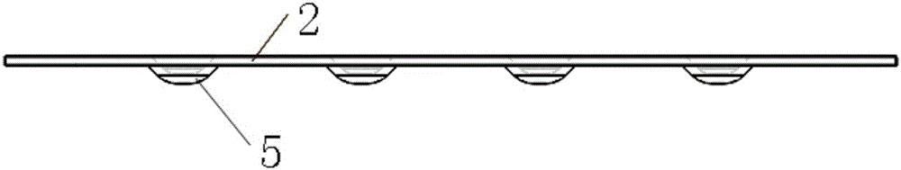
[0087] The structural parameters, quantity and position of the support bosses are optimized and designed by thermal analysis and structural analysis simulation software, and the taper bosses with non-through-hole structure are processed on the condensation cover plate by point pressing processing. The center of the upper end surface of the supporting bosses is distributed uniformly in a square lattice. Starting from the central layer of bosses, each time a layer of bosses is added, the diameter of the upper end surface of the bosses of this layer is smaller than that of the upper end surface of the bosses of the previous layer. The diameter is reduced by 1mm, and the horizontal and vertical distances of the center of the upper end surface of each layer of bosses are equal. The contact with the condensing cov...


PUM


Abstract

The invention provides a flat plate heat pipe. The flat plate heat pipe comprises an evaporation cover plate, a condensation cover plate, a liquid filling pipe and liquid absorption cores. The evaporation cover plate is of a concave table structure. A connection belt is arranged around the periphery of the top end of the concave table structure of the evaporation cover plate. The liquid absorption cores of a porous capillary structure are formed in the periphery of the inner side of the top end of the concave table structure of the evaporation cover plate, and a hydrophilic thin layer is compounded to the bottom face of the inner side of the top end of the concave table structure of the evaporation cover plate. A plurality of convex plates are arranged on the side, in contact with the evaporation cover plate, of the condensation cover plate. A hydrophobic thin layer is compounded to the positions, except for the positions with the convex tables, of the side, in contact with the evaporation cover plate, of the condensation cover plate. A through hole is formed in the outer side of the evaporation cover plate, and the liquid filling pipe is arranged in the through hole. The evaporation cover plate and the condensation cover plate are connected in a sealed mode to form a closed cavity. Through modification of the hydrophilic property of the evaporation cover plate of the flat plat heat pipe and the hydrophobic property of the condensation cover plate, and through the supporting convex plates machined on the condensation cover plate, the heat exchange capacity and stability of the flat plate heat pipe are improved.

Description

technical field [0001] The invention relates to the technical field of heat transfer and heat dissipation, in particular to a flat heat pipe and a manufacturing method thereof. Background technique [0002] With the continuous progress of micro-manufacturing technology and electronic technology, electronic devices are gradually developing towards miniaturization, compactness and high performance. It is a problem of excessive local heat flow, which seriously affects the performance of the chip. In addition, electronic devices have high requirements on temperature uniformity, and excessive temperature will cause fatigue damage to electronic devices. In order to reduce the heat generation of the chip, conventional cooling technologies such as forced convection heat exchange combined with fins and fans, semiconductor cooling, synthetic jet cooling and other new heat dissipation technologies, but the above heat dissipation technologies have been difficult to meet the heat dissip...

Claims


Application Information

Patent Timeline
Patent Type & Authority Applications(China)
IPC IPC(8): F28D15/04
CPCF28D15/04
Inventor 王长宏郑焕培林涛
Owner GUANGDONG UNIV OF TECH
Why Eureka
Try Eureka