High-frequency electron tube booster circuit

A booster circuit and electron tube technology, applied in electrical components, adjusting electrical variables, instruments, etc., can solve the problems of increased difficulty in stabilizing power supply, damage, high gain, etc., to overcome overheating damage or excessive consumption, improve performance and service life and the effect of improving the signal-to-noise ratio

Inactive Publication Date: 2016-11-23
ZHONGSHAN YUECHEN ELECTRONICS IND
View PDF10 Cites 1 Cited by
  • Summary
  • Abstract
  • Description
  • Claims
  • Application Information

AI Technical Summary

Problems solved by technology

[0004] 1) When the electron tube is working, the filament must be fully preheated and required to work under the conditions of low voltage and high current; except for the filament, the electron tube mainly works under the state of high voltage and low current, which is more difficult for the stabilized power supply. Big
[0005] 2) The front stage is mainly responsible for small signal amplification with high gain. If AC power supply is used, it is easy to be infected with AC noise, which is extremely detrimental to improving the signal-to-noise ratio
If the screen voltage is normal and unchanged, a large signal is input to the grid. As a result, due to the high resistance of the thick coating, the heat generated when the screen current flows is greater, and more electrons are "sucked" by the screen electrode to meet the screen current. Increased demand, so when the filament voltage is too low, it is easy to cause local excessive evaporation of the cathode and be damaged
Conversely, if the heating voltage is too high, the evaporation of the oxide on the entire cathode surface layer will also be accelerated, which will shorten the life of the electron tube

Method used


Image

  • High-frequency electron tube booster circuit
  • High-frequency electron tube booster circuit

Examples


Embodiment Construction

[0016] The scheme of this application is further described in conjunction with the accompanying drawings as follows:

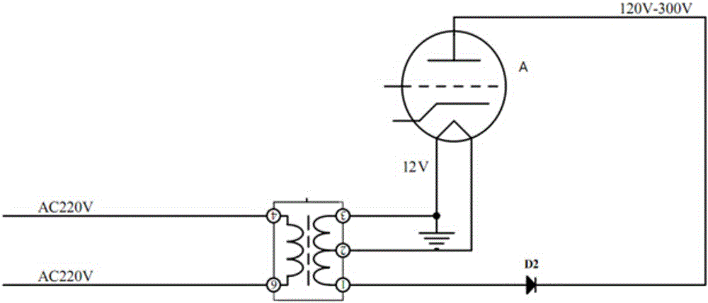
[0017] See attached figure 1 , the traditional low-frequency electronic tube power supply circuit, its input terminal is directly connected to the 220V mains, it is easy to be infected with AC noise, which is extremely unfavorable for improving the signal-to-noise ratio; and under the current power supply status in our country, it is necessary to ensure that the output It is also difficult to maintain the voltage at 6.3V, and the instability of the filament power supply will seriously affect the life of the tube.

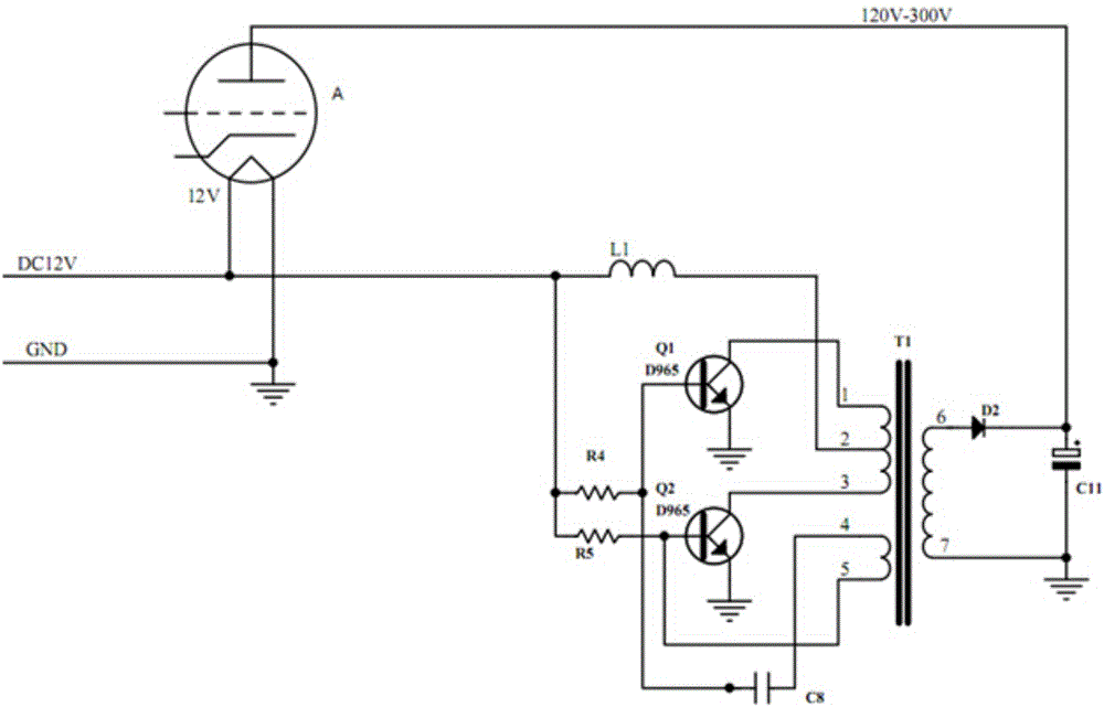
[0018] See attached figure 2 , the high-frequency tube booster circuit of the present invention has a DC voltage input terminal, and the circuit specifically includes an electronic transistor A, an inductor L1, a triode Q1, a triode Q2, a high-frequency transformer T1, a capacitor C8, an electrolytic capacitor C11, a resistor R4 and a resistor R5...


PUM


Abstract

The invention provides a high-frequency electron tube booster circuit. The high-frequency electron tube booster circuit is characterized in that the high-frequency electron tube booster circuit comprises a direct-current voltage input end and specifically comprises an electron transistor A, an inductor L1, triodes Q1 and Q2, a high-frequency transformer T1, a capacitor C8, an electrolytic capacitor C11 and resistors R4 and R5; a first primary winding of the high-frequency transformer T1 is provided with wiring terminals I, II and III; a second primary winding of the high-frequency transformer T1 is provided with wiring terminals IV and V; a first secondary winding is provided with wiring terminals VI and VII; the electrolytic capacitor C11 is connected between the wiring terminals VI and VII; a collector electrode of the triode Q1 is connected with the wiring terminal I and a base electrode of the triode Q1 is connected to the direct-current voltage input end; a collector electrode of the triode Q2 is connected with the wiring terminal III and a base electrode of the triode Q2 is connected to the direct-current voltage input end; the base electrode of the triode Q1 is connected to the wiring terminal IV through the capacitor C8; the base electrode of the triode Q2 is connected to the wiring terminal V; two electrodes of a lamp filament of the electron transistor A are connected to the direct-current voltage input end and a ground end respectively, and a plate electrode of the electron transistor A is connected with the electrolytic capacitor C11.

Description

technical field [0001] The invention relates to a high-frequency electronic tube booster circuit. Background technique [0002] The power amplifier of audio equipment is used to amplify the weak electrical signal from the signal source to drive the speaker to emit sound, which can be understood as an energy converter; from the perspective of existing technology and use requirements, the power amplifier is required to be low-consumption, High reliability and conducive to improving the various indicators of the audio system; however, the true portrayal of the existing electronic tube amplifiers is "bulky, power-consuming, and good sound quality". At this point, the electronic tube amplifier does not meet the requirements of "green environmental protection" . The technical focus of the audio amplifier lies in the power supply. A good power supply can produce good sound, which is the key to obtaining high fidelity and high signal-to-noise ratio in the pre-amplification; therefo...

Claims


Application Information

Patent Timeline
Patent Type & Authority Applications(China)
IPC IPC(8): H02M3/335
CPCH02M3/3353
Inventor 朱文锋肖杰行高立
Owner ZHONGSHAN YUECHEN ELECTRONICS IND
Why Eureka
Try Eureka