Device and method for heat recovery and utilization of waste incinerator fly ash treated by high-temperature melting method

A technology of waste incineration fly ash, high temperature melting, applied in the combustion method, incinerator, combustion type and other directions, can solve the problems of difficult engineering application and large-scale promotion, high equipment cost and operating cost, and high energy consumption of fly ash. , to achieve good economic value, reduce comprehensive energy consumption, and reduce energy consumption costs.

Active Publication Date: 2019-02-22
ANHUI TENGLONG ELECTRIC
View PDF7 Cites 2 Cited by
  • Summary
  • Abstract
  • Description
  • Claims
  • Application Information

AI Technical Summary

Problems solved by technology

However, studies have shown that the high-temperature melting method consumes a lot of energy, so the cost of fly ash treatment is very high; at the same time, the high-temperature tail gas of the melting furnace cannot be directly discharged into the atmosphere because it contains a large amount of heavy metals and soot, requiring complicated cooling, Equipment such as heavy metal removal and dust removal, the system is complex, and the cost of investment and operation and maintenance is high
High equipment and operating costs make it difficult to implement engineering applications and large-scale promotion of this technology

Method used


Image

  • Device and method for heat recovery and utilization of waste incinerator fly ash treated by high-temperature melting method
  • Device and method for heat recovery and utilization of waste incinerator fly ash treated by high-temperature melting method
  • Device and method for heat recovery and utilization of waste incinerator fly ash treated by high-temperature melting method

Examples


Embodiment 1

[0038] Device structure:

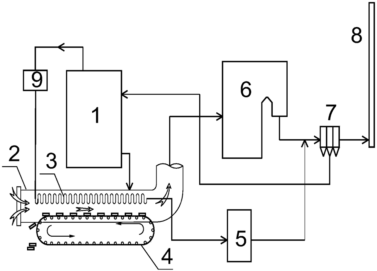
[0039] Such as figure 1 As shown, the heat energy recovery and utilization device for waste incineration fly ash treated by high-temperature melting method includes a high-temperature melting furnace 1, and the slag discharge port of the high-temperature melting furnace 1 is connected with the slag inlet port of IHE2. IHE2 is equipped with a high-temperature tail gas radiator 3 and melting The slag cooling conveying device 4, the inlet of the high-temperature tail gas radiator 3 is connected to the exhaust port of the high-temperature melting furnace 1, the outlet of the high-temperature tail gas radiator 3 is connected to the inlet of the flue gas heavy metal removal treatment equipment 5, and the high-temperature melting furnace 1 is connected to the IHE 2 is provided with denitrification equipment 9, the hot air outlet of IHE2 is connected with the combustion air supply inlet of waste incineration boiler 6, and the flue gas outlet of waste inciner...

Embodiment 2

[0047] Device structure:

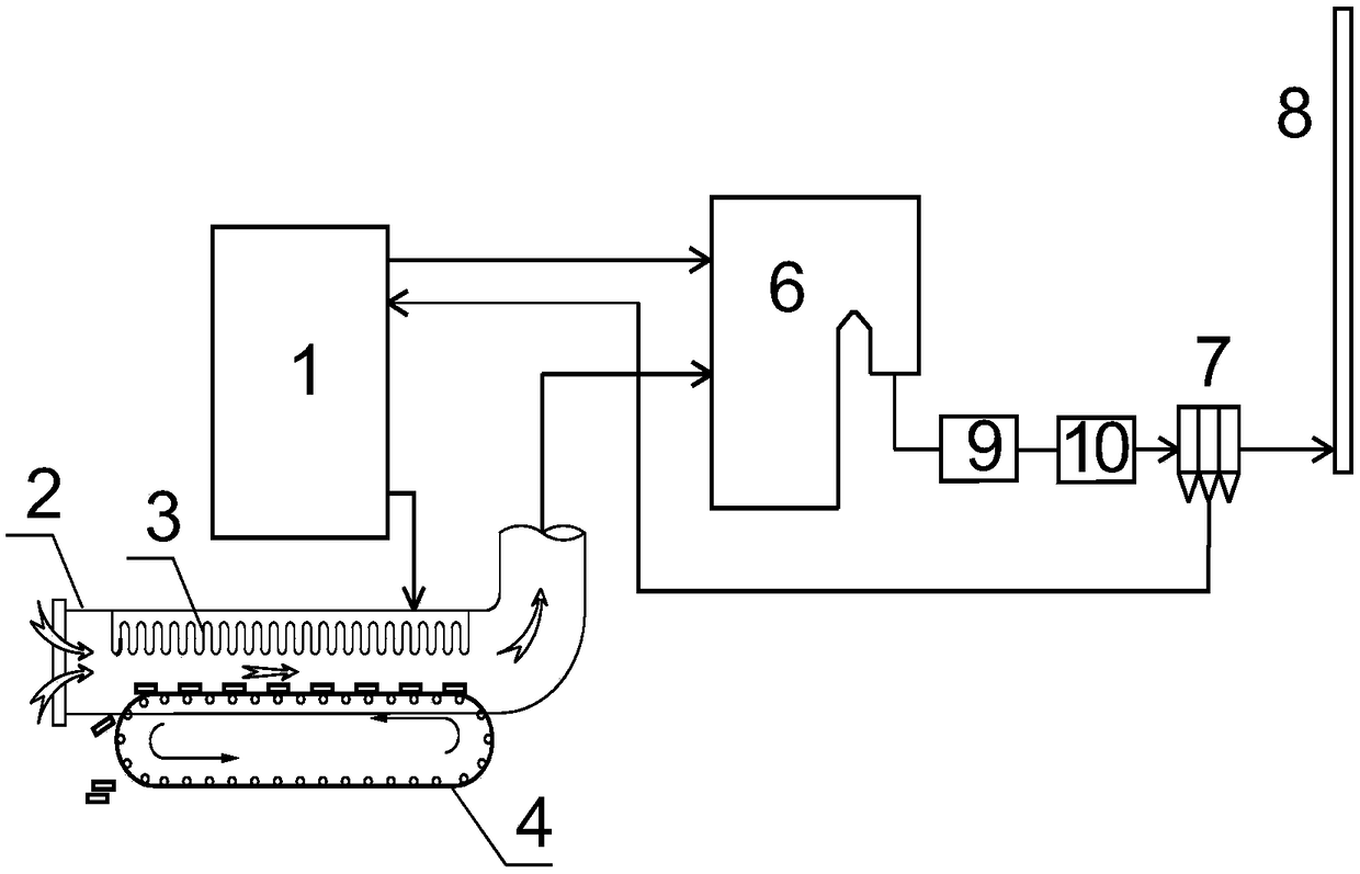
[0048] Such as figure 2 As shown, the heat energy recovery and utilization device for waste incineration fly ash treated by high-temperature melting method includes a high-temperature melting furnace 1, the slag discharge port of the high-temperature melting furnace 1 is connected with the slag inlet port of IHE 2, and a high-temperature tail gas radiator 3 is installed in IHE 2 and the slag cooling conveying device 4, the hot air outlets of the high-temperature melting furnace 1 and the IHE 2 are respectively connected with the combustion air supply inlet of the waste incineration boiler 6, and the flue gas outlet of the waste incineration boiler 6 is connected with the flue gas inlet of the dust collector 7, The fly ash collected by the dust collector 7 is connected to the high-temperature melting furnace 1 through a conveying device. The front end of the flue gas inlet of the dust collector 7 is provided with a denitrification device 9 and a deac...

Embodiment 3

[0056] Device structure:

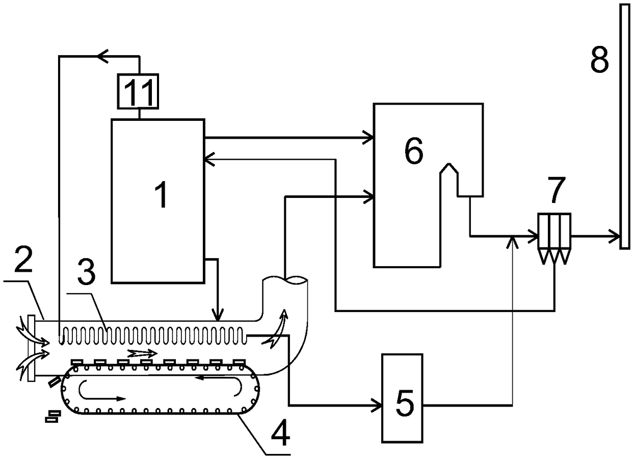
[0057] Such as image 3 As shown, the heat energy recovery and utilization device for waste incineration fly ash treated by high-temperature melting method includes a high-temperature melting furnace 1, the slag discharge port of the high-temperature melting furnace 1 is connected with the slag inlet port of IHE 2, and a high-temperature tail gas radiator 3 is installed in IHE 2 and the slag cooling transfer device 4, the exhaust port of the high temperature melting furnace 1 is provided with a tail gas component detection device 11, the inlet of the high temperature tail gas radiator 3 is connected with the exhaust port of the high temperature melting furnace 1, and the outlet of the high temperature tail gas radiator 3 is connected with the exhaust port of the high temperature melting furnace 1. The inlet of flue gas heavy metal removal treatment equipment 5 is connected, the hot air outlets of high temperature melting furnace 1 and IHE 2 are respe...


PUM


Abstract

The invention belongs to the technical field of manufacture of environmental protection equipment, and relates to a thermal energy recycling device and method for treating flying ash of a garbage incinerator by a high-temperature melting method. The device comprises a high-temperature melting furnace, an IHE, a high-temperature tail gas heat sink, a molten slag cooling and conveying device, flue gas heavy metal desorption treatment equipment, a garbage incineration boiler, a dust remover and a chimney, wherein high-temperature tail gas of the high-temperature melting furnace is delivered to the flue gas heavy metal desorption treatment equipment and is treated after being cooled; molten slag in the high-temperature melting furnace becomes glass bodies after being cooled; the glass bodies are discharged along with a conveying chain of the molten slag cooling and conveying device; and thermal energy of the high-temperature tail gas and thermal energy in the molten slag are recycled in the garbage incineration boiler and is utilized. Garbage flying ash treated by the high-temperature melting method is directly applied to the garbage incineration boiler, energy consumption cost is greatly reduced, furthermore, the tail gas treatment mode is simplified, a system is also simplified greatly, primary investment costs are reduced, and by application of the high-temperature melting method on the garbage incineration boiler, harmless treatment of the flying ash can be realized, and furthermore, the economic value is high.

Description

technical field [0001] The invention belongs to the technical field of environmental protection equipment manufacturing, and relates to a heat energy recycling device and method for processing waste incineration fly ash by high-temperature melting method. Background technique [0002] At present, a large amount of fly ash produced by waste incineration boilers is a hazardous waste strictly controlled by the state. The current typical treatment methods include cement solidification and chelating agent stabilization. After these methods, secondary pollution is not easy to occur. Using cement solidification chelating agent stabilization technology, the leaching rate of cement solidification is relatively high, and the volume of cement solidification is relatively high, which not only increases the volume of fly ash, but also requires pretreatment or addition of additives, which may affect cement. The solidification of the slurry will increase the cost, and the alkalinity of the...

Claims


Application Information

Patent Timeline
Patent Type & Authority Patents(China)
IPC IPC(8): F23G5/44F23G5/46F23J15/02
CPCF23G5/44F23G5/46F23J15/02F23J2700/003F23J2900/01007
Inventor 符仲恩陈佺
Owner ANHUI TENGLONG ELECTRIC
Why Eureka
Try Eureka