Scintillator
一种闪烁体、母体的技术,应用在闪烁体领域,能够解决闪烁体发光效率不是很高等问题,达到提高余辉特性、图像鲜明、良好拍摄的效果
- Summary
- Abstract
- Description
- Claims
- Application Information
AI Technical Summary
Problems solved by technology
Method used
Image
Examples
Embodiment 1、3-11· comparative example 1-2 and 4
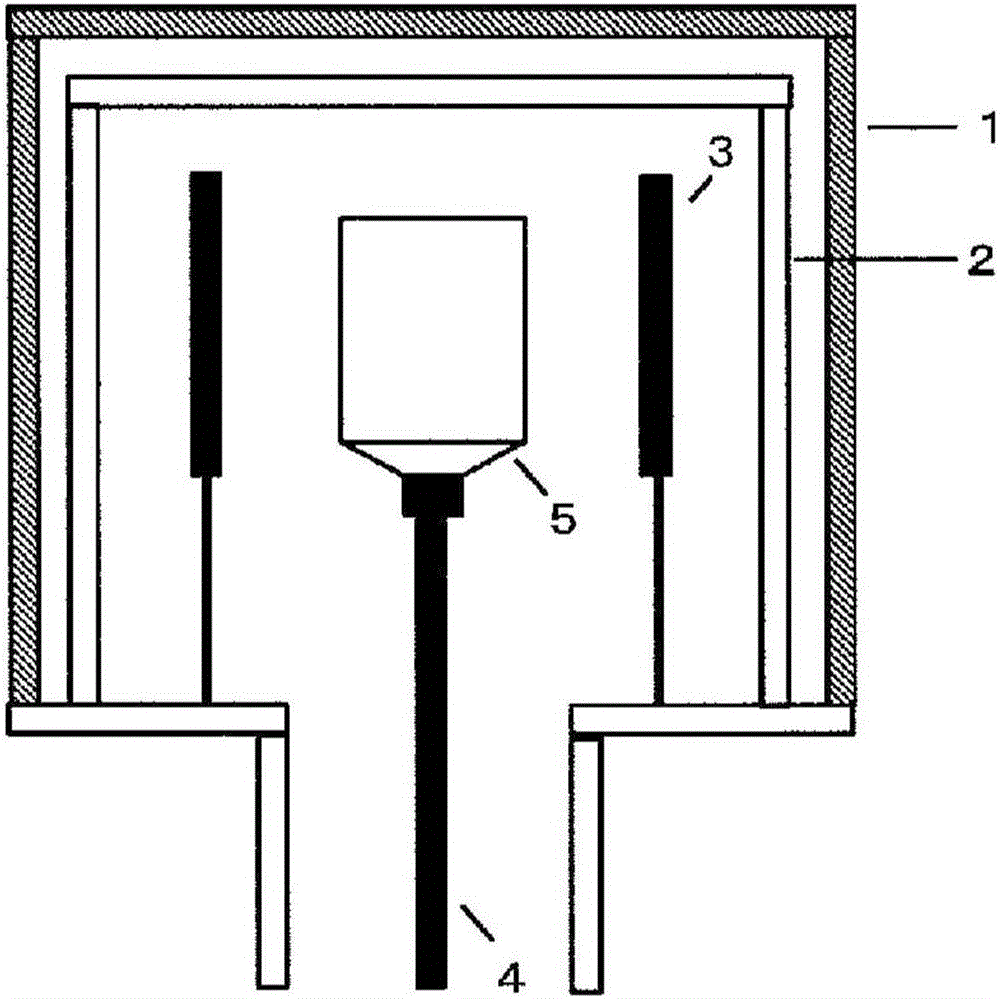
[0085] Weigh CsI powder (99.999%), TlI powder (99.999%), and BiI according to the amount shown in Table 1. 3 Powder (99.999%), use a mortar to mix and place in figure 2 In the illustrated crystal growth device, crystal growth is performed. Here, the doping amounts of Tl and Bi elements are expressed in atomic% (at. %) of the Cs element in CsI as the base material.
[0086] Crystal growth is performed by the vertical Bridgman method described below. That is, hydrofluoric acid with a hydrofluoric acid concentration adjusted to 10% was added to a quartz crucible with a main body (body portion) having a diameter of 45 mm and a length of 100 mm and a conical bottom, and washed for 5 minutes. The quartz crucible that has been washed in this way is thoroughly washed with water, and then naturally dried.
[0087] The pre-treated quartz crucible was added with the raw materials mixed with the mortar as described above, and the rotary pump and oil diffusion pump were used to vacuum to the ...
Embodiment 2 and comparative example 3
[0091] In Example 2 and Comparative Example 3, a quartz crucible with a main body diameter of 45mm and a length of 100mm with an open upper end was used. After cleaning the quartz crucible in the same manner as in Example 1, the quartz crucible was washed thoroughly with water, and it was added after natural drying. After mixing the raw materials in the mortar, place the quartz crucible in the furnace, and circulate N in the furnace under the atmosphere 2 And adjust the flow rate. In this state, it was heated to 300°C, and then kept for 12 hours to remove the moisture contained in the raw material, and then the measurement sample was obtained in the same manner as in Example 1 above. At this time, control circulation N 2 The oxygen concentration of the processing atmosphere is changed by the flow rate at the time.
Embodiment 12
[0093] In Example 12, a measurement sample was obtained in the same manner as in Example 1, except that a quartz crucible with a cylindrical portion having a diameter of 120 mm and a length of 230 mm and a conical bottom was used.
[0094]
[0095] (Results and discussion)
[0096] A part of the crystals obtained in Example 1-12 was pulverized and subjected to powder XRD measurement. As a result, the crystals obtained in Examples 1-12 were all CsI single-phase crystals, and no other phases were found.
[0097] From the above-mentioned examples and the results of experiments carried out by the present inventors so far, it can be seen that regarding the scintillator having a crystal made of CsI (cesium iodide) as a matrix and containing Tl, Bi, and O, by comparing the above-mentioned crystals with respect to The ratio of the O content b of I and the Bi content a of Cs in the above crystal (a / b) is adjusted to 0.005×10 -4 ~200×10 -4 At the same time, the Bi content concentration a relat...
PUM
| Property | Measurement | Unit |
|---|---|---|
| diameter | aaaaa | aaaaa |
| length | aaaaa | aaaaa |
Abstract
Description
Claims
Application Information
 - R&D
- Intellectual Property
- Life Sciences
- Materials
- Tech Scout
- Unparalleled Data Quality
- Higher Quality Content
- 60% Fewer Hallucinations
Browse by: Latest US Patents, China's latest patents, Technical Efficacy Thesaurus, Application Domain, Technology Topic, Popular Technical Reports.
© 2025 PatSnap. All rights reserved.Legal|Privacy policy|Modern Slavery Act Transparency Statement|Sitemap|About US| Contact US: help@patsnap.com


