

Package for power storage device and power storage device
A technology for storage equipment and outer packaging, which is applied in the direction of battery box/cover material, transportation and packaging, battery box/coat, etc., to achieve the effect of shortening the aging (curing) time, shortening the production time, and improving the insulation
- Summary
- Abstract
- Description
- Claims
- Application Information
AI Technical Summary
Problems solved by technology
Method used
Image

Examples
Embodiment 1
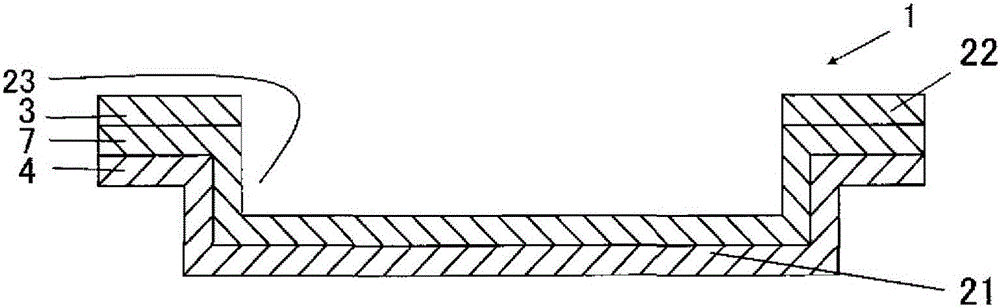
[0146] Coating a chemical conversion treatment solution containing polyacrylic acid, phosphoric acid, and compounds of chromium and fluorine on both sides of an aluminum foil with a thickness of 30 μm, and drying at 150°C to achieve a chromium adhesion amount of 3 mg / m 2 .
[0147] On one side of the aluminum foil (metal foil layer) that has undergone the chemical conversion treatment, a polyester-urethane adhesive is applied. Thereafter, a biaxially stretched polyethylene terephthalate (PET) film (acid-resistant layer) having a thickness of 6 μm was bonded to the polyester-urethane adhesive-coated surface.
[0148] Next, 100 parts by mass of maleic acid-modified polypropylene (melting point 90° C., maleic anhydride content 0.3 mass %), 1 part by mass of toluene diisocyanate, Resin composition of 0.1 parts by mass of silica (anti-blocking agent) and 0.2 parts by mass of 5-butyloxazole-2,4-dione (lubricant), followed by curing by heating at 80°C In 1 day, an insulating layer ...
Embodiment 2
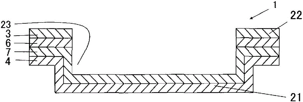
[0151] Coating a chemical conversion treatment solution containing polyacrylic acid, phosphoric acid, and compounds of chromium and fluorine on both sides of an aluminum foil with a thickness of 25 μm, and drying at 150°C to achieve a chromium adhesion amount of 3 mg / m 2 .
[0152] On one side of the aluminum foil (metal foil layer) that has undergone the chemical conversion treatment, a polyester-urethane adhesive is applied. Thereafter, a biaxially stretched polyethylene terephthalate (PET) film (acid-resistant layer) having a thickness of 2 μm was bonded to the polyester-urethane adhesive-coated surface.
[0153] Next, 100 parts by mass of maleic acid-modified polypropylene (melting point 90° C., maleic anhydride content 0.3 mass %), 1 part by mass of toluene diisocyanate, A resin composition of 0.1 parts by mass of silica (anti-blocking agent) and 0.2 parts by mass of 5-butyloxazole-2,4-dione (lubricant) was cured by heating at 80° C. for 1 day to form a thickness of 3 μm...
Embodiment 3
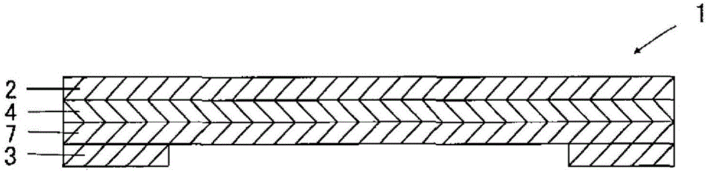
[0156]Instead, use a laminated film of a biaxially stretched polyethylene terephthalate (PET) film with a thickness of 6 μm / a biaxially stretched polyamide film with a thickness of 20 μm (the polyamide film is placed on the inside (side of the aluminum foil)) A biaxially stretched PET film with a thickness of 6 μm is coated with 20 parts by mass of epoxy melamine resin, 0.3 parts by mass of silicon dioxide (anti-blocking agent), 0.2 parts by mass of polyethylene wax (lubricant), and 64 parts by mass of toluene (solvent). Parts by mass and 16 parts by mass of MEK (solvent) were used instead of the coating solution containing maleic acid-modified polypropylene, and then heated at 200°C for 1 minute to thermally cure and form epoxymelamine with a thickness of 3 μm. The thermally cured layer of the resin was obtained in the same manner as in Example 1 except that image 3 The outer packaging materials for the electrical storage equipment shown.
PUM
| Property | Measurement | Unit |
|---|---|---|
| adhesion amount | aaaaa | aaaaa |
| melting point | aaaaa | aaaaa |
| melting point | aaaaa | aaaaa |
Abstract
Description
Claims
Application Information