Integrated Soil Remediation Photocatalytic Reactor

A photocatalytic reactor and soil remediation technology, applied in the field of integrated soil remediation photocatalytic reactors, can solve the problems of insufficient contact between photocatalysts and soil pollutants, difficult separation of soil particles, harsh photocatalytic reaction conditions, etc. To achieve efficient and stable processing effect, avoid a large amount of loss, and achieve the effect of small footprint

Active Publication Date: 2018-11-23
HOHAI UNIV
View PDF7 Cites 0 Cited by
  • Summary
  • Abstract
  • Description
  • Claims
  • Application Information

AI Technical Summary

Problems solved by technology

[0005] 1. Large power consumption: Plasma discharge photocatalytic reactors require a high-voltage power supply system; traditional photocatalytic reactors use ultraviolet mercury lamps, and the air blowing system has a large amount of aeration
[0006] Second, the mass transfer effect of photocatalysts and pollutants on soil particles is poor: studies have shown that the size of soil particles has an important impact on the photocatalytic degradation efficiency of organic pollutants in soil, and smaller-sized soil particles have a better effect on photocatalysts. Large contact area, the photocatalytic degradation efficiency is higher; traditional photocatalytic reactors use magnetic stirring or paddle stirring, which cannot fully contact the photocatalyst and soil pollutants
[0007] 3. Difficulty in photocatalyst recovery: traditional photocatalytic reactors use photocatalyst particle powder, which is difficult to separate from soil particles, resulting in a large loss of photocatalyst, which will increase operating costs and easily produce secondary pollution
[0008] Fourth, the photocatalytic reaction conditions are harsh and the operation is cumbersome: the Fenton photocatalytic reactor requires the reaction conditions to be acidic (the optimum pH is about 3), and iron sludge is easily generated in the reactor, which requires subsequent processing steps

Method used


Image

  • Integrated Soil Remediation Photocatalytic Reactor
  • Integrated Soil Remediation Photocatalytic Reactor

Examples


Embodiment Construction

[0031] The present invention will be further described below in conjunction with the accompanying drawings. The following examples are only used to illustrate the technical solution of the present invention more clearly, but not to limit the protection scope of the present invention.

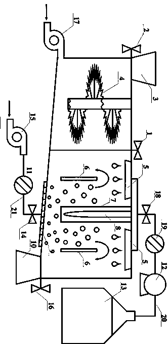
[0032] Such as figure 1 As shown, the integrated soil repair photocatalytic reactor includes a reactor shell, a cutter 4, a spraying device, two deflectors 6, an LED light 8 and an aeration device; the reactor shell includes a soil crushing chamber and a three-phase cycle photocatalytic degradation chamber; two reaction chambers are arranged in the housing, the soil inlet is connected to the soil crushing chamber, and the soil outlet is connected to the three-phase cycle photocatalytic degradation chamber.

[0033] The soil crushing chamber is connected to the three-phase cycle photocatalytic degradation chamber, and the cutter 4 is rotatably connected to the top wall of the soil crushing chamb...


PUM


Abstract

An integrated soil restoration photocatalytic reactor, a reactor shell thereof comprising a soil grinding chamber and a three-phase cyclic photocatalytic degradation chamber; the soil grinding chamber is connected to the three-phase cyclic photocatalytic degradation chamber, and a cutting blade (4) is rotatably connected to an inner wall of the soil grinding chamber so as to efficiently, rapidly, and uniformly grind soil; a soil inlet is opened on the inner wall of the soil grinding chamber, and a soil outlet is opened on a bottom wall of the three-phase cyclic photocatalytic degradation chamber; a spraying device is arranged above the three-phase cyclic photocatalytic degradation chamber, an aeration device is arranged below the chamber, and an ultraviolet LED light (8) is arranged in the middle; guide plates (6) are symmetrically arranged on both sides of the ultraviolet LED light (8) so that three phases of gas, liquid and solid may be uniformly mixed and may flow circularly; a surface of the guide plate (6) is coated with a photocatalyst titanium dioxide, thus solving the problem wherein a catalyst is difficult to recycle; the device integrates the functions of cutting and refining soil and photocatalytic restoration of soil, and has the advantages of a small area, a simple structure, a mild reaction condition, absence of secondary pollution, and an efficient and stable treatment effect.

Description

technical field [0001] The invention relates to an integrated photocatalytic reactor for soil restoration and belongs to the technical field of soil restoration. Background technique [0002] Polycyclic aromatic hydrocarbons are a class of chemical substances composed of more than two aromatic rings (linear or clustered), usually containing only carbon and nitrogen elements, but nitrogen, sulfur, oxygen and other elements can enter the benzene ring through substitution reactions to form hetero ring aromatic compounds. PAHs are mainly produced by incomplete combustion and pyrolysis of organic matter, and their sources can be divided into natural sources and man-made sources. Natural sources include forest fires, volcanic eruptions, etc.; man-made sources include motor vehicle exhaust emissions, residential wood burning, petroleum catalytic Cracking, industrial fossil fuel combustion, etc. So far, more than 200 kinds of polycyclic aromatic hydrocarbons have been discovered, ...

Claims


Application Information

Patent Timeline
Patent Type & Authority Patents(China)
IPC IPC(8): B09C1/08B01J19/12
CPCB01J19/12B09C1/08
Inventor 李轶张弛郭燕飞李杰吴文祥
Owner HOHAI UNIV
Why Eureka
Try Eureka