Perovskite laminated solar cell and preparation method thereof

A technology of perovskite cells and tandem solar, applied in circuits, photovoltaic power generation, electrical components, etc., can solve the problems of complex preparation process of HIT-type tandem cells, narrow photon energy absorption range, difficult industrial production, etc. The effect of improved conversion efficiency, enhanced optoelectronic properties, and enhanced photon absorption capacity

Inactive Publication Date: 2017-02-15
DALIAN UNIV OF TECH
View PDF8 Cites 18 Cited by
  • Summary
  • Abstract
  • Description
  • Claims
  • Application Information

AI Technical Summary

Problems solved by technology

The problems faced by the HIT laminated battery are that the preparation process is complicated, the cost is expensive, and it is difficult to put it into industrial production
The stacked battery composed of ordinary perovskite and front-contact silicon cells, in which the per

Method used


Image

  • Perovskite laminated solar cell and preparation method thereof

Examples


Embodiment 1

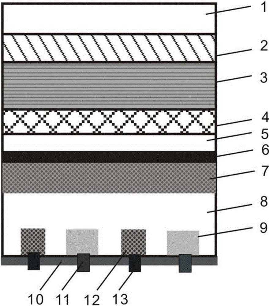
[0037] like figure 1 , the present embodiment provides a method for manufacturing a perovskite solar cell with multiple light-absorbing layers, the cell comprising: conductive glass 5, an electron transport layer 4, a perovskite multiple light-absorbing layer 3, a hole transport layer 2, Top conductive layer 1, anti-reflection passivation layer 6, phosphorus diffusion front field 7, silicon substrate 8, back surface passivation layer 10, p + Diffusion area 9, n ++ heavily doped region 12, p + Diffusion area electrodes 11, n ++ Heavily doped regional electrodes 13 . The perovskite multiple light-absorbing layer structure in this example contains three perovskite monolayers, and each layer contains a single perovskite molecular component. From bottom to top, they are perovskite I layer, perovskite II layer, Perovskite III layer. These three perovskite molecules have partly the same composition, layer I is AMX 3 Perovskite layer, layer II is AMX 2 Y 1 , Tier III for AMX ...

Embodiment 2

[0055] This embodiment provides a method for manufacturing a perovskite solar cell with multiple light-absorbing layers, the battery comprising: conductive glass 5, electron transport layer 4, perovskite multiple light-absorbing layer 3, hole transport layer 2, top Conductive layer 1, anti-reflection passivation layer 6, phosphorus diffusion front field 7, silicon substrate 8, back surface passivation layer 10, p + Diffusion area 9, n ++ heavily doped region 12, p + Diffusion area electrodes 11, n ++ Heavily doped regional electrodes 13 . The perovskite multiple light-absorbing layer structure in this example contains a perovskite monolayer, and its composition is (C 6 h 5 C 2 h 4 NH 3 ) 2 PB 4 Its absorption bandwidth is 2.3eV, and its layer thickness is 500nm.

[0056] 1) Select an n-type silicon substrate with a resistivity of 2-5Ω·cm, and remove the damaged layer.

[0057] 2) Carry out double-sided texturing on the silicon wafer with potassium hydroxide NaOH alk...


PUM

PropertyMeasurementUnit
Thicknessaaaaaaaaaa
Thicknessaaaaaaaaaa
Resistivityaaaaaaaaaa

Abstract

The invention discloses a perovskite laminated solar cell and a preparation method thereof. The structure of the perovskite laminated solar cell comprises a perovskite cell (1) and a full back contact type cell (2) from top to bottom, wherein the perovskite cell comprises multiple light absorption layers; the structure of the top-layer perovskite cell is composed of conductive glass, an electron transporting layer, the multiple light absorption layers, a hole transporting layer and a top part conductive layer; and the structure of the bottom-layer full back contact type cell is composed of an antireflection passivation layer, a phosphorus diffusion front field, a back surface passivation layer, p+ diffusion regions, n++ heavily-doped regions, p+ diffusion region electrodes, and n++ heavily-doped region electrodes. The perovskite laminated solar cell is simple in preparation method, low in cost and high in energy conversion efficiency. Since the top-layer perovskite cell comprising the multiple light absorption layers has higher light absorption capability than an ordinary perovskite cell, the front surface of the full back contact type cell is not sheltered by grid lines, and the two cells can achieve higher photon collection capability in a wide spectral range after being laminated, thereby significantly increasing the conversion efficiency.

Description

technical field [0001] The invention belongs to the technical field of solar cell preparation, and in particular relates to a method for preparing a stacked solar cell formed by connecting a perovskite cell and a cell with a full back contact structure in series. Background technique [0002] The invention of solar cells provides the possibility for people to utilize clean and safe solar energy. Because traditional solar cells mostly use a single-junction structure of a single material, such as crystalline silicon cells, copper indium gallium tin cells, quantum dot cells, organic cells, etc. With the continuous enrichment of research and development work over the years, it has become difficult to continue to increase the efficiency of single-junction cells. The theoretical conversion efficiency of solar cells depends on the bandgap width of photovoltaic materials. The stacked cell structure can combine different sub-cells, which can break through the conversion efficiency ...

Claims


Application Information

Patent Timeline
IPC IPC(8): H01L51/42H01L51/48H01L31/0687H01L31/18
CPCH01L31/0687H01L31/1804H10K85/30H10K30/451Y02E10/544Y02E10/549Y02E10/547Y02P70/50
Inventor 魏一刘爱民
Owner DALIAN UNIV OF TECH
Why Eureka
Try Eureka