
Silicate fluorescent ceramic with full-spectrum emission effect and preparation method thereof

A technology of fluorescent ceramics and silicate, which is applied in the field of silicate fluorescent ceramics and its preparation, can solve the problems of low color rendering index of white light LEDs, decreased light output efficiency of devices, weak absorption of excitation light, etc., and achieves high luminous efficiency, emission Wide wavelength range and good thermal stability

Active Publication Date: 2017-03-22
CHANGCHUN INST OF OPTICS FINE MECHANICS & PHYSICS CHINESE ACAD OF SCI
View PDF1 Cites 9 Cited by
  • Summary
  • Abstract
  • Description
  • Claims
  • Application Information

AI Technical Summary

Problems solved by technology

But due to the activated ion Ce 3+ replace Ca 2+ There is a charge mismatch at the lattice site, Ce 3+ The concentration of ions entering the host lattice is very low, resulting in weak absorption of excitation light by the phosphor. People try to enhance the absorption by increasing the thickness of the phosphor, but the light extraction efficiency of the device is significantly reduced due to the multiple scattering of light in the phosphor. , which greatly limits its application in high-power white LEDs
On the other hand, current fluorescent ceramics mainly focus on rare earth aluminates with garnet structure, such as Re 3 al 3 o 12 (Re=Lu, Y, Tb and Gd), and they all emit light from a single active ion. The white LED synthesized by it also has problems such as low color rendering index and high color temperature due to the lack of red light components.

Method used


Image

  • Silicate fluorescent ceramic with full-spectrum emission effect and preparation method thereof
  • Silicate fluorescent ceramic with full-spectrum emission effect and preparation method thereof
  • Silicate fluorescent ceramic with full-spectrum emission effect and preparation method thereof

Examples


preparation example Construction

[0036] The preparation method of the powder in the embodiment of the present invention is direct ball milling of raw materials, but the preparation method of the mixed powder of the present invention is not limited to the above preparation method, and wet chemical methods such as sol-gel method and uniform precipitation well-known to those skilled in the art can also be used. synthesis.

[0037] The preparation method of the ceramic body in the embodiment of the present invention is dry pressing forming, but the present invention has no special limitation on the method of dry pressing forming, it can be a forming method well known to those skilled in the art. In the embodiment of the present invention, adopt Axial one-way pressurization is used for dry press forming, and axial two-way pressurization can also be used for dry press forming.

[0038] The ceramic phosphor can also be prepared by a two-step sintering method, that is, the powder is first sintered to obtain Ca 3-x-y...

Embodiment 1

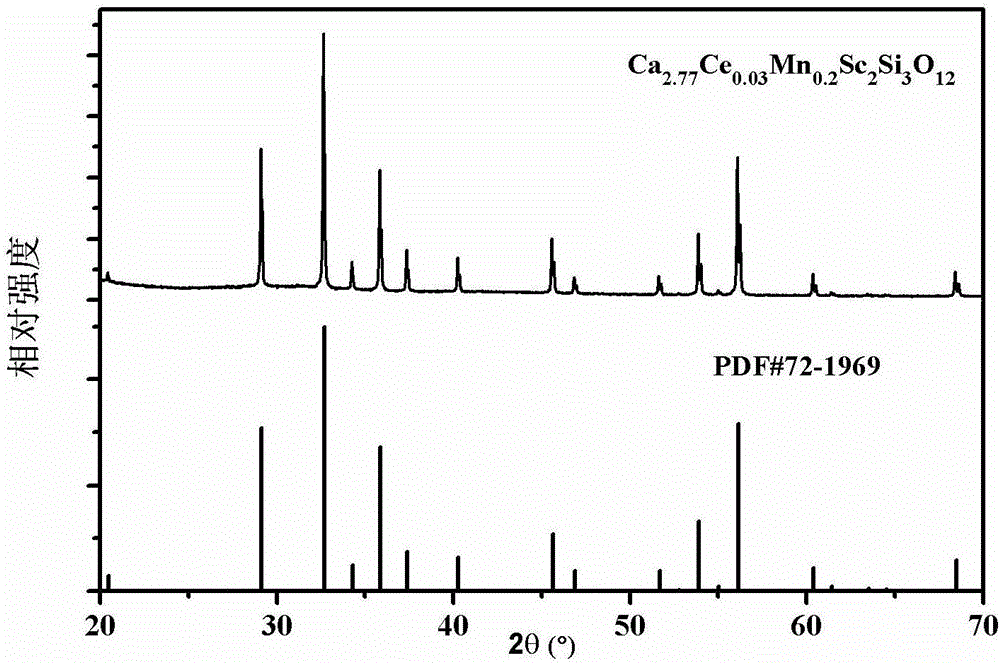
[0043] Ca 2.969 Ce 0.001 mn 0.03 sc 2 Si 3 o 12 preparation of

[0044] Weigh CaCO according to stoichiometric ratio 3 : 14.903 g, Sc 2 o 3 : 6.895 g, SiO 2 : 9.013 g, CeO 2 : 0.087 g, MnCO 3 : 0.1724 g. Use zirconia balls and ball milling tanks to grind and mix the raw materials with absolute ethanol as the medium until the average particle size of the powder is less than 0.5 μm; dry and sieve the slurry obtained after ball milling; The sieved powder was first dry-pressed in an axial unidirectional pressure mold with a pressure of 20 MPa and a holding time of 2 minutes, and then pressed into a green body by cold isostatic pressing (pressure of 220 MPa and holding time of 2 minutes). Put the biscuit into a vacuum furnace for sintering: first, raise the temperature to 1000°C at 4°C / min, keep it for 5 hours, and decompose the carbonate; To 1600 ℃, keep warm for 10h, remove pores and densify. The vacuum sintered samples were placed in a hot-press sintering furnace f...

Embodiment 2

[0047] Ca 2.85 Ce 0.05 mn 0.1 sc 2 Si 3 o 12 preparation of

[0048] Weigh CaCO according to stoichiometric ratio 3 , Sc 2 o 3 , SiO 2 , CeO 2 and MnCO 3 , using zirconia balls and ball milling tanks, and using absolute ethanol as the medium to grind and mix the raw materials until the average particle size of the powder is less than 0.5 μm; the slurry obtained after ball milling is dried and sieved; then, an appropriate amount of The sieved powder is first dry-pressed in an axial unidirectional pressure mold with a pressure of 20 MPa and a holding time of 2 minutes, and then pressed into a green body by cold isostatic pressing (pressure of 220 MPa and holding time of 2 minutes). Put the biscuit into a vacuum furnace for sintering: first, raise the temperature to 1000°C at 4°C / min, keep it for 5 hours, and decompose the carbonate; To 1600 ℃, keep warm for 10h, remove pores and densify. The vacuum sintered samples were placed in a hot-press sintering furnace for ho...


PUM


Abstract

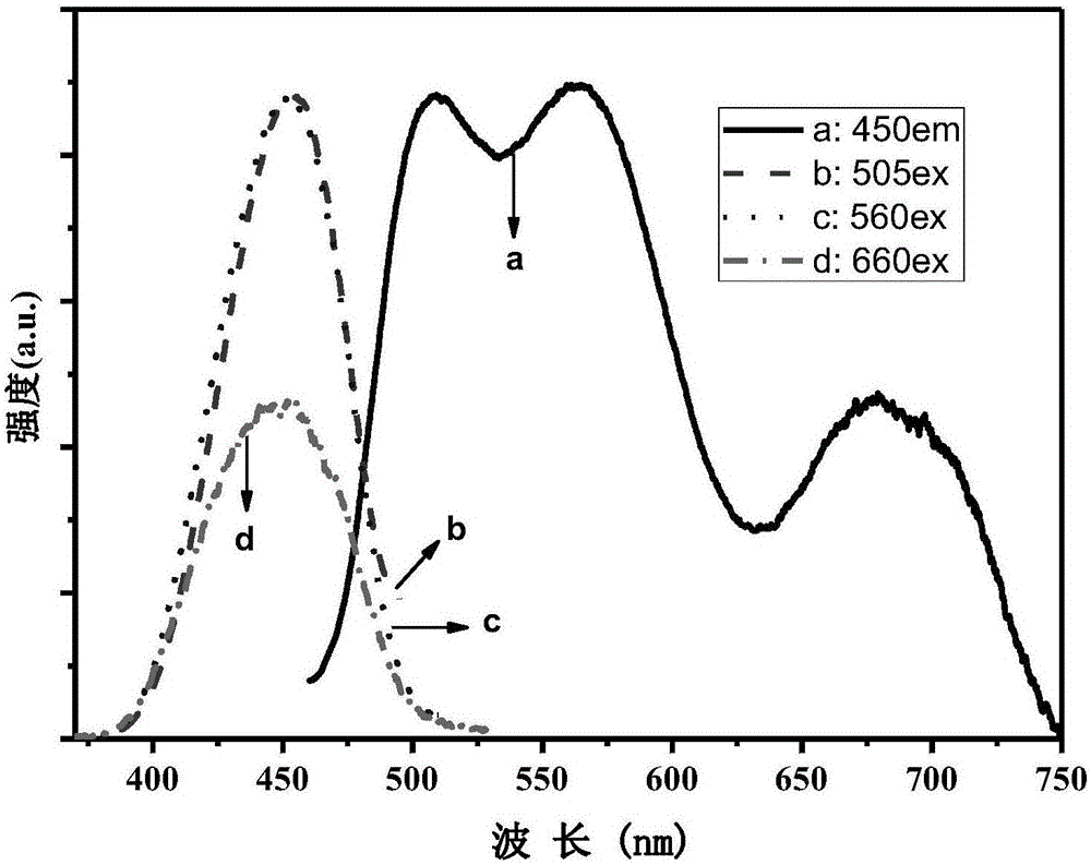
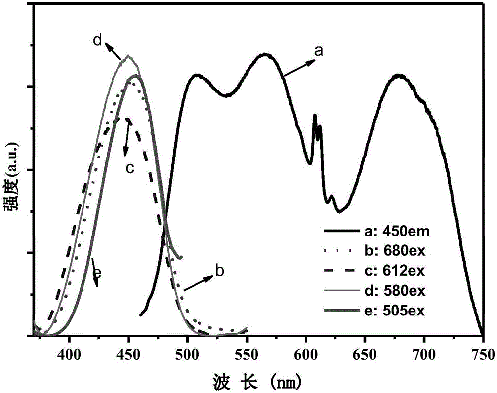
The invention provides silicate fluorescent ceramic with a full-spectrum emission effect. The chemical formula of the silicate fluorescent ceramic is shown as following: Ca3-x-y-z-mCexPryMnzNamSc2Si3O12 (I), wherein x is greater than or equal to 0.001 and less than or equal to 0.2, y is greater than or equal to 0 and less than or equal to 0.1, z is greater than or equal to 0.03 and less than or equal to 0.4, and m is greater than or equal to 0 and less than or equal to 0.3. The silicate fluorescent ceramic adopts a garnet crystal structure, belongs to a cubic crystal system, and has a space group of Ia3d. The silicate fluorescent ceramic provided by the invention is stable in physicochemical property; under the effective excitation of blue light, the emission wavelength scope of the silicate fluorescent ceramic is broad; blue-green light, yellow light, red light and deep-red light are covered in the spectrum; a low-color-temperature high-color-rendering white-light LED can be manufactured by using such single fluorescent ceramic, namely the silicate fluorescent ceramic; the problem about reabsorption caused by the mixing of multi-color fluorescent powder can be solved; the silicate fluorescent ceramic can be applied to high-power blue-light LEDs or LD pumping white-light LEDs; and the high-end display and illumination requirements can be met.

Description

technical field [0001] The invention relates to the technical field of luminescent materials, in particular to a silicate fluorescent ceramic with full-spectrum emission and a preparation method thereof. Background technique [0002] White LEDs are considered to be the fourth-generation lighting sources that are expected to replace traditional lighting due to their advantages of energy saving, environmental protection, long life, small size, and short response time. At present, there are mainly two schemes for synthesizing white light LEDs. One is to use red, green, and blue primary color LEDs to synthesize white light through the principle of color mixing; the other is to use one or more phosphors to emit blue or ultraviolet light from LEDs. light is converted to white light. The former scheme is only used in the field of large-screen display because of its complicated control circuit and high manufacturing cost. At present, the commercialized white light LED mainly adopt...

Claims


Application Information

Patent Timeline
IPC IPC(8): C04B35/22C04B35/622C04B35/64C04B35/645C09K11/79
CPCC04B35/22C04B35/622C04B35/64C04B35/645C04B2235/3224C04B2235/3229C04B2235/442C04B2235/662C04B2235/77C04B2235/95C04B2235/9646C09K11/7774Y02B20/00
Inventor 张家骅肖文戈张霞张晟张亮亮郝振东潘国徽
Owner CHANGCHUN INST OF OPTICS FINE MECHANICS & PHYSICS CHINESE ACAD OF SCI
Learn More