
Technical method for denitration of sintering flue gas

A technology of sintering flue gas and process method, which is applied in the field of sintering flue gas denitrification treatment process, can solve the problems of little progress, high operating cost, high operating cost, etc., and achieve the effect of strong applicability and reduced operating cost

Active Publication Date: 2017-03-22
钢研晟华科技股份有限公司
View PDF6 Cites 24 Cited by
  • Summary
  • Abstract
  • Description
  • Claims
  • Application Information

AI Technical Summary

Problems solved by technology

However, little progress has been made in the construction of sintering flue gas denitrification. There are less than 10 sintering denitrification devices reported in my country. Among them, it is recognized that the activated carbon method has a better removal effect. Activated carbon technology can simultaneously remove SOx, NOx, and dioxins and Other harmful volatiles, but the process requires large investment and high operating costs, making it difficult to popularize
Other Selective Catalytic Reduction (SCR) denitrification methods that are maturely used in the power industry, denitrification technology cannot be realized due to the low temperature of the burnt tail gas. If the exhaust gas is heated to the temperature required for the catalytic reaction, the energy consumption will be huge, and the operating cost will also increase.
[0003] In terms of waste heat utilization in the sintering process, on the one hand, the energy consumption of the sintering process is second only to blast furnace ironmaking, accounting for about 15% of the total energy consumption of iron and steel enterprises; on the other hand, the proportion of waste heat utilization in the sintering process is very low, only 35% to 45%. About 0.9GJ of heat energy per ton of sinter is not utilized

Method used


Image

  • Technical method for denitration of sintering flue gas
  • Technical method for denitration of sintering flue gas
  • Technical method for denitration of sintering flue gas

Examples


Embodiment 1

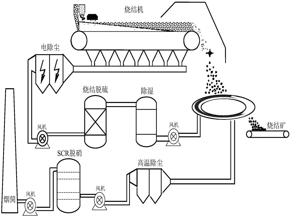
[0023] The sintering flue gas at 120-130°C is discharged from the desulfurization tower after wet desulfurization, the tail gas temperature is 55-60°C, and the water content is 75mg / m 3 , the steam with high moisture content is dehumidified through the lithium bromide and lithium chloride salt solution contained in the plastic material, and the relative humidity of the flue gas after dehumidification is 20% to 30%;

[0024] During the dehumidification process, the dehumidification solution absorbs the moisture in the tail gas, and its own concentration decreases, and the dehumidification solution is concentrated and regenerated by using the waste heat of the sintering flue gas pipeline at 120-130°C;

[0025] The desulfurized tail gas after dehumidification first passes through the pipeline heat exchanger to exchange heat with the sintering flue gas and sintering ore. After the heat exchange, the tail gas temperature is about 100°C;

[0026] The heat exchange exhaust gas is blo...

Embodiment 2

[0034] The sintering flue gas at 120-130°C is discharged from the dust bag after dry desulfurization, the tail gas temperature is about 90°C, and the relative humidity is about 40%;

[0035] Desulfurization tail gas passed through anhydrous CaCl 2 The dehumidification device further dehumidifies so that the relative humidity is below 20%;

[0036] CaCl 2 Heat release after moisture absorption, tail gas temperature remains at around 90°C after dehumidification, CaCl after moisture absorption 2 Dehydration and regeneration of tail gas after heat exchange by waste heat boiler;

[0037] The heat exchange tail gas is blown in by the fan in the high temperature section of the belt cooler to exchange heat with the sinter, and the sinter in the low temperature section is cooled by natural wind, and a partition wall is added in the belt cooler to prevent the desulfurization tail gas from mixing with the cold air in the low temperature section;

[0038] After the heat exchange, the t...

Embodiment 3

[0045] The sintering flue gas at 120-130°C is discharged from the dust bag after dry desulfurization, the tail gas temperature is about 90°C, and the relative humidity is about 40%;

[0046]The heat exchange tail gas exchanges heat with the sinter through the vertical tank type sinter cooling device. After the heat exchange, the temperature of the desulfurized tail gas is above 320°C. The cold air is cut into the vertical tank to continue cooling the sinter to below 100°C, and the sinter is discharged and sent to Blast furnace smelting.

[0047] After heat exchange, the tail gas is dedusted by the electric precipitator to make the dust concentration of the flue gas meet the requirements of selective catalytic reduction and denitrification;

[0048] Ammonia vapor is introduced into the denitrification device with built-in catalyst for reduction and denitrification. The removal rate of NOx in the flue gas is above 85%. The reaction equation of selective catalytic reduction and d...


PUM


Abstract

The invention relates to a technical method for denitration of sintering flue gas. The method is particularly applicable to the treatment of the flue gas generated by sintering of iron ore in the steel and iron industry. The method can be used as the supporting construction for an enterprise with an existing sintering desulfuration technique, and can also be newly established together with a selected mature desulfuration technique of the sintering flue gas. Sintered and desulfurated tail gas is subjected to dehumidification and then used for heat exchanging of high-temperature sintering ore in a ring cooling machine, a straight-line cooler and a vertical-tank type sintering ore cooling device. The heat exchanging tail gas is dedusted and kept at the temperature of 300 DEG C or over. Selective catalytic reduction (SCR) is used for denitration of the tail gas, the removal rate of Nox in the flue gas is 85% or over, and the temperature of the denitrated tail gas is higher than 250 DEG C and can be used for waste heat electricity generation or heat-air sintering of a sintering machine, ignition and combustion supporting, and sintering ore preheating. The technical method for denitration of the sintering flue gas has the advantages that treatment capacity is large, applicability is high, sensible heat of the sintering ore is adequately used, and operating cost is low.

Description

technical field [0001] The invention relates to the treatment of desulfurization tail gas in the iron ore sintering process, and is particularly suitable for a treatment process method for denitrification of sintering flue gas. Background technique [0002] my country's iron and steel production is mainly based on the blast furnace-converter long process, sintering ore accounts for about 70% to 75% of the blast furnace charge, and the dust emission and SO 2 The emissions of industrial dust and SO in my country account for about 2 At the same time, the sintering process also discharges a large amount of harmful substances such as NOx, HF, HCl, heavy metals and dioxins, becoming the main source of air pollution. At present, the technology of sintering flue gas desulfurization is mature, and there are many methods. There are about 650 sets of sintering desulfurization facilities built and put into operation in China. However, little progress has been made in the construction ...

Claims


Application Information

Patent Timeline
IPC IPC(8): F27D17/00
CPCY02P10/25
Inventor 郭玉华齐渊洪严定鎏林万舟周和敏于恒
Owner 钢研晟华科技股份有限公司
Learn More