
A method for controlling a permanent magnet brushless DC motor driver

A permanent magnet brushless DC and motor driver technology, which is applied in the direction of motor generator control, electronic commutation motor control, electromechanical brake control, etc., can solve the problem of poor dynamic response performance of motors, low control accuracy of DC motors, and reduced robot System anti-interference ability and other issues, achieve good control accuracy and dynamic response performance, solve the contradiction between overshoot and rapidity, and improve the effect of anti-interference ability

Active Publication Date: 2019-03-29
STATE GRID CHONGQING ELECTRIC POWER CO ELECTRIC POWER RES INST +3
View PDF4 Cites 0 Cited by
  • Summary
  • Abstract
  • Description
  • Claims
  • Application Information

AI Technical Summary

Problems solved by technology

[0002] When the robot conducts inspections, it often encounters obstacles such as walls or obstacles; in this environment, the robot needs to drive the motor to overcome the obstacles. This robot uses a permanent magnet DC motor to drive the control system; but the control accuracy of the DC motor is not good. High, causing the robot to fail to cross obstacles correctly, or due to the poor dynamic response performance of the motor, the anti-interference ability of the robot system is reduced. Therefore, a DC motor driver control method with dynamic response performance is required

Method used


Image

  • A method for controlling a permanent magnet brushless DC motor driver
  • A method for controlling a permanent magnet brushless DC motor driver
  • A method for controlling a permanent magnet brushless DC motor driver

Examples


Embodiment 1

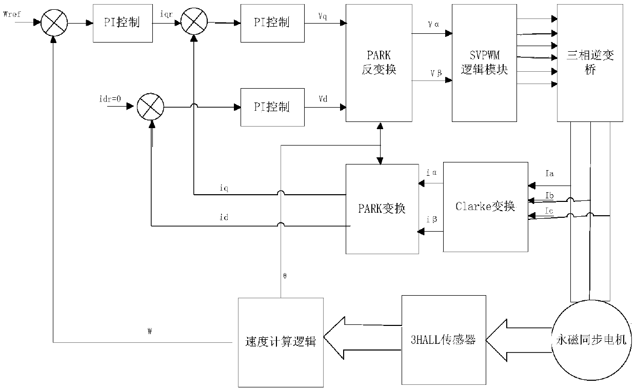
[0075] As shown in the figure, the permanent magnet brushless DC motor driver control method provided in this embodiment includes a processor DSP, a HALL sensor, a DC motor, a PID controller, a PARK conversion module, and a PARK inverter. Conversion module, three-phase inverter, Clark conversion module, speed calculation logic module:

[0076] The drive of this embodiment uses a serial port or a resistance memory motor for speed regulation, directly sends a control command to a DSP, and uses a DSP timer to adopt a PWM comparison output mode to output 3 groups of independent complementary PWM signals. The motor phase current sampling module directly inputs the current sampling voltage signal to the ADC pin of the DSP, and the CPU obtains the corresponding sampling value. After the PID controller, the PARK conversion module, and the PARK inverse conversion module are converted through internal software, the PWM control signal output is generated, thereby Realize current loop contro...

Embodiment 2

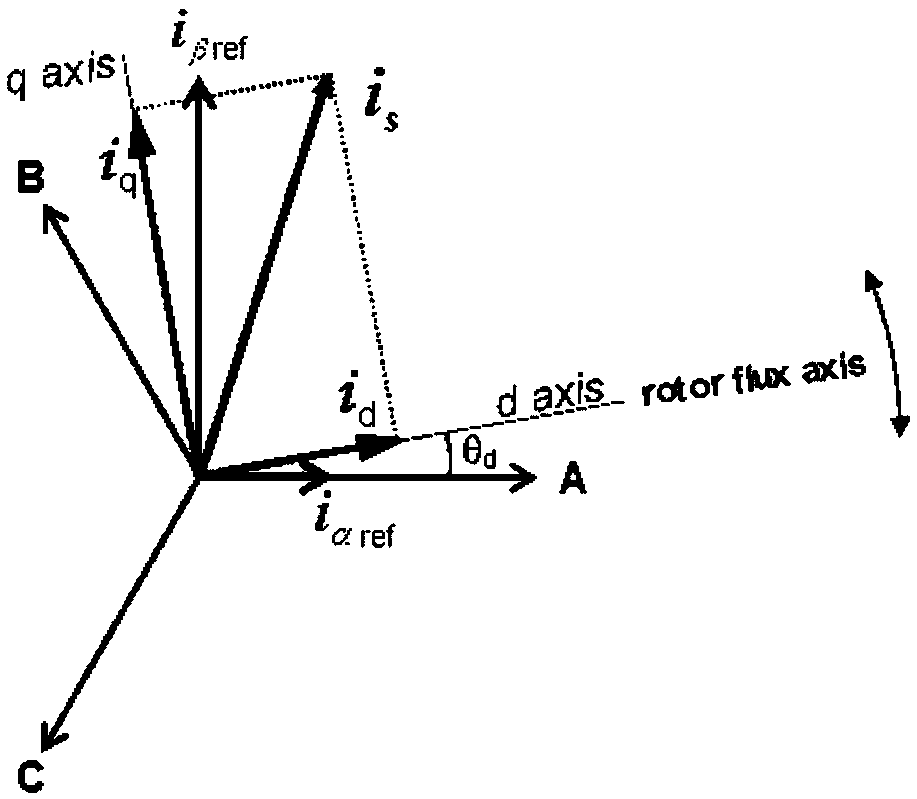
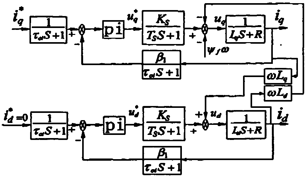
[0118] The basic idea of ​​the FOC control algorithm used in this embodiment is to decompose the current vector into two mutually perpendicular and independent vectors on the field-oriented coordinates. d (Magnetic current component that produces magnetic flux) and i q (Torque current component that produces torque) Control i d And i q Then the torque of the motor can be controlled. According to the control method of rotor flux orientation (i d =0) Make the stator current vector lie on the q-axis without d-axis component. Torque T e And i q A linear relationship. Therefore, as long as i q Controlling can achieve the purpose of torque control. Clark transformation is the coordinate transformation of the stator three-phase winding from the stationary ABC axis system to the stationary αβ axis system. The Park transformation means that the two-phase stationary coordinate is equivalent to the two-phase rotating coordinate through the transformation matrix, such as figure 2 As shown...


PUM


Abstract

The invention discloses a permanent magnet brushless DC motor driver control method. The method is used for control of a motor drive servo control system. The system has relatively good control accuracy and dynamic response performance. The method comprises the steps of firstly reading values of three commutation HALLs through software to obtain an actual position of a rotor when a motor is started, detecting an angular position omega<ref> of the rotor through a rotor position sensor after starting, and simultaneously calculating a speed n of the rotor; detecting a stator current FOC control algorithm to obtain detection values i<d> and i<q>; outputting AC / DC shaft voltage values u<d> and u<q> through a PI adjuster separately, generating voltage values u<alpha> and u<beta> after coordinate transformation to obtain an SVPWM drive signal; and finally outputting sixth paths of control pulse signals and driving six MOSs to drive the motor. The permanent magnet brushless DC motor driver control method is suitable for control of an intelligent obstacle avoidance robot and is achieved by adopting a DSP processor; the control process is achieved through a vector control strategy of which direct axis current is zero; the contradiction between overshoot and the rapidity is solved; the anti-jamming capability of the system is improved; and the high-performance requirement is met.

Description

Technical field [0001] The invention relates to the field of DC motors, in particular to a method for controlling permanent magnet brushless DC motor drivers. Background technique [0002] During inspections, robots often encounter obstacles such as walls or obstacles; in this environment, the robot needs to drive a motor to overcome obstacles. This robot uses a permanent magnet DC motor to drive the control system; however, the control accuracy of the DC motor is not High, resulting in the robot being unable to cross obstacles correctly, or due to the poor dynamic response performance of the motor, which reduces the anti-interference ability of the robot system. Therefore, a DC motor drive control method with dynamic response performance is needed. Summary of the invention [0003] The purpose of the present invention is to provide a permanent magnet brushless DC motor driver; the DC motor driver control method has the characteristics of high dynamic response performance. [0004]...

Claims


Application Information

Patent Timeline
Patent Type & Authority Patents(China)
IPC IPC(8): H02P21/14H02P21/00
Inventor 周小龙宋伟侯兴哲罗春雷邓帮飞胡晓锐石为人甘建峰王成疆王大洪肖杰李新平李杰
Owner STATE GRID CHONGQING ELECTRIC POWER CO ELECTRIC POWER RES INST
Learn More