Cryogenic separation system for separating mixed gas

A technology of cryogenic separation and mixed gas, applied in cold treatment separation, educts, refrigeration and liquefaction, etc., can solve the problems of poor operation adaptability, high process energy consumption, large equipment investment, etc. , High separation efficiency, and the effect of reducing investment

Active Publication Date: 2017-05-10
HANGZHOU HANGYANG
View PDF11 Cites 24 Cited by
  • Summary
  • Abstract
  • Description
  • Claims
  • Application Information

AI Technical Summary

Problems solved by technology

[0003] Currently, CO and H 2 Most of the patents published by the cryogenic separation method are CO / H 2 In the single-tower process of binary components, the maximum purity of CO obtained by separation can reach 98.5%, which is relatively low in purity and cannot meet the requirements of high-purity CO product gas (≥99%), while for impurity N 2 、CH 4 The further purification and separation of the process has been mentioned in the Chinese patent (publication number CN201480063530.9), but the disadvantages of this patent are that the process energy consumption is high, the equipment investment is large, and the operation adaptability is not very good

Method used


Image

  • Cryogenic separation system for separating mixed gas

Examples


Embodiment

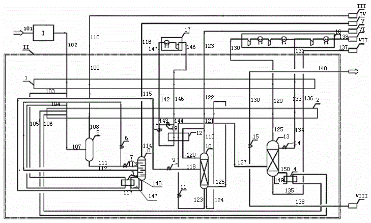
[0031] Example: figure 1 As shown, the present invention is used to separate the cryogenic separation device and method for the mixed gas containing carbon monoxide, hydrogen, methane and a small amount of nitrogen, including molecular sieve purification unit I and cryogenic separation cold box II for removing impurity gases, the deep cryogenic separation The cold separation cold box II includes the first main heat exchanger 1, the second main heat exchanger 2, the hydrogen separation tank 5, the stripping tower 8 and the set reboiler 3, the denitrification tower 10 and the set condenser 12, The demethanizer 13 and the set reboiler 4 , the nitrogen refrigeration circulation system 17 , 141 - 146 and the liquid nitrogen channels 138 , 139 , 140 . Contains carbon monoxide (30%~90%), hydrogen (70%~10%), methane, a small amount of nitrogen (≤3%) and trace CO 2 Mixed gas with methanol (pressure: 2.0MPaG~8.0MPaG) enters molecular sieve purification unit I through pipeline 101 to re...


PUM


Abstract

The invention discloses a cryogenic separation system for separating a mixed gas. The system mainly comprises two parts, that is, a molecular sieve purification unit and a cold box of a cryogenic separation device, wherein the mixed gas at least containing carbon monoxide, hydrogen, methane and a small amount of nitrogen communicates with an inlet pipeline of the molecular sieve purification unit, the molecular sieve purification unit sequentially communicates with a first main heat exchanger, a tower bottom reboiler of a stripping tower, a tower bottom reboiler of a demethanizing tower, and a second main heat exchanger in the cold box of the cryogenic separation device through a first pipeline and then is connected to a middle inlet of a hydrogen separation tank after impurities easy to condense at a low temperature, of carbon dioxide, methyl alcohol and water, are removed, and three hydrogen-enriched gas pipelines are connected out from the top of the hydrogen separation tank and communicate with an external hydrogen-enriched gas collection system after a hydrogen-enriched gas is reheated by the two main heat exchangers to recover a cold quantity; and two liquid pipelines are connected out from the bottom of the hydrogen separation tank, one liquid pipeline communicates with a middle inlet pipeline of the stripping tower through a first throttle valve and the second main heat exchanger, and the other liquid pipeline communicates with an upper inlet pipeline of the stripping tower through a second throttle valve.

Description

technical field [0001] The invention relates to a cryogenic separation system for separating mixed gas containing carbon monoxide, hydrogen, methane and a small amount of nitrogen, belonging to the field of low-temperature gas separation. Background technique [0002] Syngas (CO and H 2 ) is an important basic chemical raw material, which can be used to synthesize ethylene glycol, acetic acid, acetic anhydride, phosgene, dimethyl acetate, formic acid, propionic acid, oxalic acid and dimethylformamide. With the continuous development of new C1 chemical technology, the synthesis process has a great impact on CO and H 2 Purity requirements gradually increase, syngas (CO and H 2 ) is mostly obtained by transforming coal as raw material. According to the difference of coal types, coal gasification usually contains a small amount of methane and nitrogen after transformation, and the requirements for these two gases are relatively high for subsequent synthesis devices, so high P...

Claims


Application Information

Patent Timeline
Patent Type & Authority Applications(China)
IPC IPC(8): F25J3/02F25J5/00
CPCF25J3/0223F25J3/0233F25J5/00F25J2215/14F25J2210/60F25J3/0252F25J3/0257F25J3/0261F25J2200/40F25J2200/70F25J2200/72F25J2200/76F25J2205/04F25J2210/42F25J2270/12F25J2270/42F25J2270/904
Inventor 秦燕郝雅博梁维好曲涛张宽
Owner HANGZHOU HANGYANG
Why Eureka
Try Eureka