High spatial resolution magnetic field detection device and method

A high spatial resolution, detection device technology, applied in the direction of the size/direction of the magnetic field, can solve the detection principle and system construction complexity of the detection device, the limited detection sensitivity, the limited spatial resolution of the detection magnetic field, and the inability to achieve miniaturization, etc. problem, to achieve the effect of simple structure, easy function and simple method

Active Publication Date: 2017-05-24
UNIV OF SHANGHAI FOR SCI & TECH
View PDF6 Cites 2 Cited by
  • Summary
  • Abstract
  • Description
  • Claims
  • Application Information

AI Technical Summary

Problems solved by technology

The prior technology has considerable advantages, but there are some essential deficiencies: 1) The principle of the magnetic field detection device is based on the superconducting quantum interference device to detect the magnetic field, and the two physical phenomena of magnetic flux quantization and Josephson tunneling effect are the detection principles. A low-temperature refrigeration system is necessary, usually using liquid nitrogen or liquid helium refrigeration, and the system structure is complex; 2) The detection sensitivity of the detection device is limited by the detection principle and the complexity of system construction, and the flexibility for magnetoencephalography detection is poor; 3) The device is large in size, Unable to achieve miniaturization, high construction cost, limited spatial resolution of the detection magnetic field, affecting the scope of use

Method used


Image

  • High spatial resolution magnetic field detection device and method

Examples


Embodiment Construction

[0017] The present invention will be further described below with reference to the drawings and embodiments.

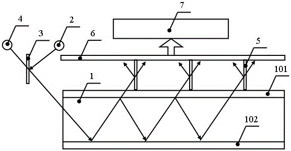
[0018] Such as figure 1 As shown, a high spatial resolution magnetic field detection device includes an atomic gas chamber 1, a polarization non-uniform distribution vector beam source 2, a beam deflection scanner 3, a detection light source 4, a photodetector 6, and a processing analysis unit 7. The bottom layer 102 and the top layer 101 of the atomic gas chamber 1 are provided with reflective films. The top layer 101 is provided with a photodetector 6, which is connected to the processing and analysis unit 7, and the atomic gas chamber 1 is provided with a polarized non-uniform distribution vector beam source 2. Beam deflection scanner 3, detection light source 4.

[0019] The polarization non-uniform distribution vector light source 2 is a radial polarization circular polarization composite laser light source or an azimuth polarization circular polarization composite l...


PUM


Abstract

The invention relates to a high spatial resolution magnetic field detection device and a detection method. The detection method comprises the steps that: 1) reflective films are arranged on the bottom layer and the top layer of an atomic gas chamber; 2) a beam propagation direction of a polarized non-uniform distribution vector beam changes when the polarized non-uniform distribution vector beam passes through a beam deflection scanner, and the polarized non-uniform distribution vector beam is incident from the side surface of the atomic gas chamber to realize multiple reflection of dynamic atomic vapor pumping; 3) a probe light source emits a probe beam incident from the side surface of the atomic gas chamber, and part of probe light is transmitted out of the top layer through transmission to form a probe beam array; 4) a photoelectric detector transmits an array signal to an information processing analysis unit after the probe beam array undergoes light splitting by means of a polarizing beam splitter; 5) and the step 4) is carried out repeatedly during the pump route scanning process, and the information processing analysis unit analyzes photoelectric distribution information of spatial difference of data, thereby realizing high spatial resolution magnetic field detection. The high spatial resolution magnetic field detection device and the detection method have the advantages of simple method, high sensitivity, large amount of detection information, dynamic pumping, high spatial resolution and the like, and do not require a low-temperature refrigeration system.

Description

Technical field [0001] The invention relates to a magnetic field detection device and method, in particular to a field used in biomedicine, geological survey, resource exploration, earthquake prediction, industrial field, navigation and positioning, material analysis, marine engineering, quantum sensing, brain magnetic core magnetism, etc. High-sensitivity magnetic field detection in medium. Background technique [0002] Instruments for measuring magnetic fields are called magnetometers, magnetometers, and Gauss meters. The physical quantity describing the magnetic field in the International System of Units is the magnetic induction, and the unit is Tesla. In earth sciences, Nat (nT) is commonly used as the unit of measurement. The commonly used unit is Gauss. Magnetic field detection is widely used in biomedicine, geological survey, resource exploration, earthquake prediction, industrial field, navigation and positioning, material analysis, ocean engineering, quantum sensing, b...

Claims


Application Information

Patent Timeline
Patent Type & Authority Applications(China)
IPC IPC(8): G01R33/02
CPCG01R33/02
Inventor 高秀敏曾祥堉苗玉詹秋芳张荣福
Owner UNIV OF SHANGHAI FOR SCI & TECH
Why Eureka
Try Eureka