Device and method for eliminating static electricity on microsphere surface
A microsphere and electrostatic technology, applied in electrostatic, electrical components, plasma and other directions, can solve the problems of surface oxidation of microspheres, introduction of impurities, etc., and achieve the effect of comprehensive coating, avoiding oxidation and convenient operation.
- Summary
- Abstract
- Description
- Claims
- Application Information
AI Technical Summary
Problems solved by technology
Method used
Image

Examples
Embodiment 1
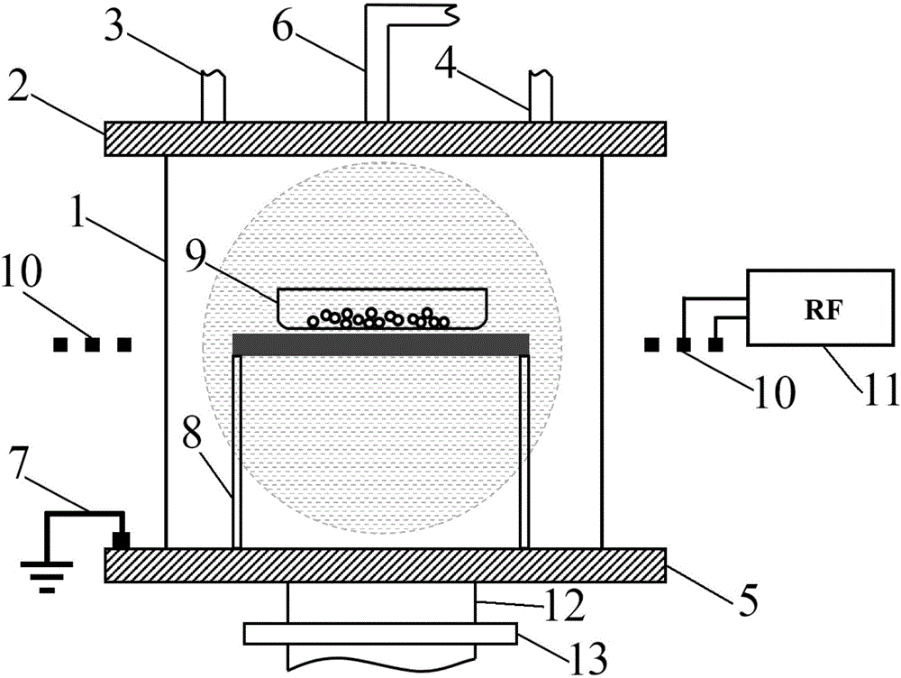
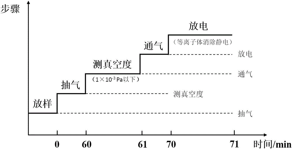
[0029] The method for eliminating the static electricity on the surface of the microspheres, firstly, configure an appropriate amount of microsphere samples to be processed in the tray 9, and place the tray 9 in the quartz resonant cavity 1. The relative positions of the tray 9 and the antenna 10 are adjusted so that the tray 9 is in the center of the plasma source area.
[0030] Secondly, vacuumize the quartz resonant cavity 1 through the vacuum pumping port 12, so that the air pressure in the quartz resonant cavity 1 is evacuated to 1×10 -3 Pa below, to ensure that the number of oxygen atoms contained in the quartz resonator 1 is sufficiently small. Then, the discharge gas, specifically hydrogen gas, is injected into the quartz resonant cavity 1 through the gas inlet 6, and the flow rate of the hydrogen gas injection is 10 ml / min. The air pressure in the quartz resonant cavity 1 is measured by the resistance unit 3 and the ionization unit 4 , and the air pressure in the qua...
Embodiment 2
[0034] The operation steps of this embodiment are basically the same as those of Embodiment 1, except that helium is used as the discharge gas. The advantage of using helium discharge is that the plasma generated by helium is chemically inert and will not have any chemical reaction with the microsphere sample to be treated.
Embodiment 3
[0036] The method for eliminating the static electricity on the surface of the microspheres, firstly, configure an appropriate amount of microsphere samples to be processed in the tray 9, and place the tray 9 in the quartz resonant cavity 1. The relative positions of the tray 9 and the antenna 10 are adjusted so that the tray 9 is in the center of the plasma source area.
[0037] Secondly, vacuumize the quartz resonant cavity 1 through the vacuum pumping port 12, so that the air pressure in the quartz resonant cavity 1 is evacuated to 1×10 -3 Below Pa. Then, the discharge gas, specifically argon gas, is injected into the quartz resonant cavity 1 through the gas inlet 6 at a flow rate of 20 ml / min. The air pressure in the quartz resonant cavity 1 is measured by the resistance unit 3 and the ionization unit 4 , and the air pressure in the quartz resonant cavity 1 is adjusted to 40Pa by using the gate valve 13 .
[0038] Again, when the air pressure in the quartz resonant cavit...
PUM
 Abstract
Description
Claims
Application Information
 - R&D
- Intellectual Property
- Life Sciences
- Materials
- Tech Scout
- Unparalleled Data Quality
- Higher Quality Content
- 60% Fewer Hallucinations
Browse by: Latest US Patents, China's latest patents, Technical Efficacy Thesaurus, Application Domain, Technology Topic, Popular Technical Reports.
© 2025 PatSnap. All rights reserved.Legal|Privacy policy|Modern Slavery Act Transparency Statement|Sitemap|About US| Contact US: help@patsnap.com