Preparation method for polymer composite electrolyte membrane

A composite electrolyte membrane and polymer technology, applied in the field of polymer materials, can solve the problems of poor surface uniformity, complex preparation process, and increased surface resistance of composite membranes, achieve low surface roughness, clear application prospects, and comprehensive The effect of performance improvement

Active Publication Date: 2017-06-09
TORAY ADVANCED MATERIALS RES LAB CHINA
View PDF10 Cites 5 Cited by
  • Summary
  • Abstract
  • Description
  • Claims
  • Application Information

AI Technical Summary

Problems solved by technology

[0007] In Patent Document 4, in order to improve the situation that acidification is prone to occur when ePTFE is combined with polymers by spraying or impregnating methods, and the impregnation adequacy and uniformity of the obtained composite membranes are difficult to achieve, an improved preparation of composite membranes is proposed. The continuous coating method can improve the production efficiency of the composite film
[0008] However, in the methods for preparing composite membranes by combining polymer electrolytes and porous membranes proposed by the above-mentioned patent documents 1 to 4, the influence of the viscosity of the polymer solution on the impregnation situation is not clearly mentioned.
However, the situation often encountered in practice is: when a high-viscosity solution is used, the surface tension of the solution is very high. When the porous membrane is impregnated, due to the capillary phenomenon of the pores, it is hindered by the excessive surface tension of the solution itself, and the solution is difficult to enter. The inside of the channel, which leads to unsatisfactory impregnation and low filling rate; when a low-viscosity solution is used, although the surface tension of the solution is reduced at this time, the capillary phenomenon of the channel is not easily hindered, and the solution is easy to impregnate into the inside of the channel, but Due to the low viscosity of the solution, the solution is not easy to cover the surface of the porous membrane, resulting in an increase in the surface roughness of the composite membrane and an increase in the surface resistance when in contact with the electrode; although the above phenomenon can be improved by repeated soaking or scraping coating, the preparation process changes. It is more complex and the surface uniformity of the composite film is deteriorated due to multiple treatments, and the overall thickness of the composite film is also difficult to uniformly control below 25 microns

Method used


Image

  • Preparation method for polymer composite electrolyte membrane
  • Preparation method for polymer composite electrolyte membrane
  • Preparation method for polymer composite electrolyte membrane

Examples


Embodiment 1

[0097]

[0098] (1) Raw materials

[0099] Polymer electrolyte A solution: Nafion solution F1;

[0100] Polymer electrolyte B solution: Nafion solution F2;

[0101] Porous membrane: expanded polytetrafluoroethylene porous membrane PM1.

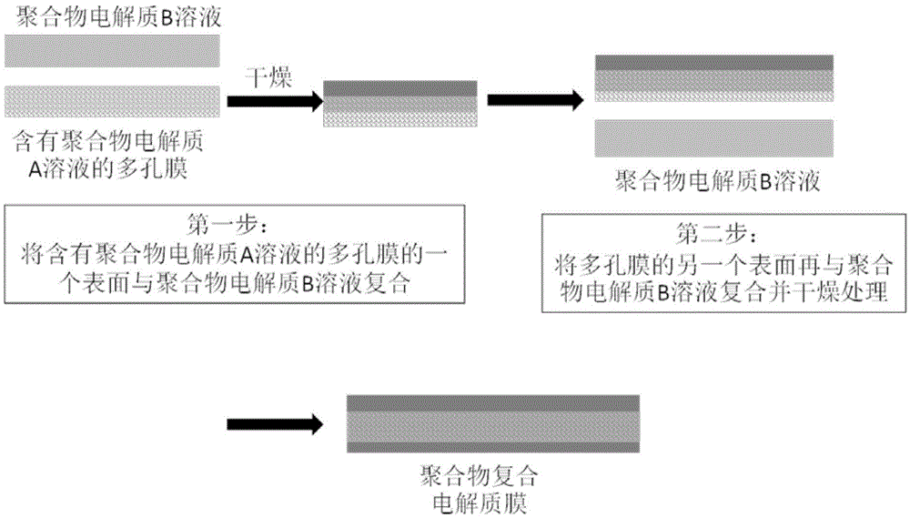
[0102] (2) Preparation of porous membrane containing polymer electrolyte A solution

[0103] After fixing the porous membrane with an outer frame, the polymer electrolyte A solution was used to coat the two surfaces respectively three times to obtain a porous membrane containing the polymer electrolyte A solution. The content of the polymer electrolyte A solution in the porous membrane was 60% of the saturated liquid absorption capacity of the porous membrane.

[0104] (3) Composite

[0105] On one surface of the fixed porous membrane containing the polymer electrolyte A solution obtained in step (2), cast the polymer electrolyte B solution and dry it in a vacuum oven at 60°C (vacuum degree 100Pa), and then dry it in another The polymer...

Embodiment 2

[0112]

[0113] (1) Raw material

[0114] Polymer electrolyte A solution: sulfonated polyetheretherketone SPEEK1 / N-methylpyrrolidone solution, the viscosity at 25°C is 50 centipoise;

[0115] Polymer electrolyte B solution: sulfonated polyetheretherketone SPEEK1 / N-methylpyrrolidone solution, the viscosity at 25°C is 1000 centipoise;

[0116] Porous membrane: expanded polytetrafluoroethylene porous membrane PM2.

[0117] (2) Preparation of porous membrane containing polymer electrolyte A solution

[0118] Submerge the porous membrane into the polymer electrolyte A solution, take it out after standing for 10 minutes, and fix it with an outer frame to obtain a porous membrane containing the polymer electrolyte A solution. The content of the polymer electrolyte A solution in the porous membrane is 100% of the saturated liquid absorption capacity of the porous membrane.

[0119] (3) Composite:

[0120] First, use a scraper with a thickness of 100 microns to scrape and coat th...

Embodiment 3

[0127]

[0128] (1) Raw material

[0129] Polymer electrolyte A solution: sulfonated polyetheretherketone SPEEK2 / N-methylpyrrolidone solution, the viscosity at 25°C is 99 centipoise;

[0130] Polymer electrolyte B solution: sulfonated polyetheretherketone SPEEK3 / N-methylpyrrolidone solution, the viscosity at 25°C is 8000 centipoise;

[0131] Porous membrane: expanded polytetrafluoroethylene porous membrane PM3.

[0132] (2) Preparation of porous membrane containing polymer electrolyte A solution

[0133] The porous membrane is fixed with an outer frame, and then the polymer electrolyte A solution is dripped on the surface of the porous membrane, and after the solution is completely absorbed, a porous membrane containing the polymer electrolyte A solution is obtained. The content of the polymer electrolyte A solution in the porous membrane was 40% of the saturated liquid absorption capacity of the porous membrane.

[0134] (3) Composite:

[0135] First, use a scraper with...


PUM

PropertyMeasurementUnit
Viscosityaaaaaaaaaa
Viscosityaaaaaaaaaa
Thicknessaaaaaaaaaa

Abstract

The invention discloses a preparation method for a polymer composite electrolyte membrane. The preparation method comprises the following steps: compounding a porous membrane containing a low-viscosity polymer electrolyte A solution and a high-viscosity polymer electrolyte B solution. The viscosity of the solution is controlled, and the polymer composite electrolyte membrane prepared by the preparation method has a high filling ration and low surface roughness, so that the comprehensive performances of the polymer electrolyte are greatly improved, and the application prospect is clearer.

Description

technical field [0001] The invention belongs to the field of polymer materials, and in particular relates to a preparation method of a polymer composite electrolyte membrane. Background technique [0002] A polymer electrolyte is a polymer ion conductor containing dissociable ionic groups. Because of its good conductivity and the unique characteristics of light weight, good elasticity and easy film formation of polymers, it has become a hot spot in the research and development of chemical power sources in recent years. At present, polymer electrolytes are mainly used in fields such as lithium-ion batteries or fuel cells. In order to improve the efficiency and output power density of the battery, it is urgent to reduce the resistance of the polymer electrolyte membrane and improve the conductivity. Researchers have conducted various discussions on this, and there are usually the following two approaches: (1) The method of reducing the film thickness is used to reduce the re...

Claims


Application Information

Patent Timeline
IPC IPC(8): H01M8/1069H01M8/1044H01B1/12
CPCH01B1/122H01M8/1044H01M8/1069H01M2300/0082Y02E60/50
Inventor 杨扬王晋韩文冈本由明子白井秀典出原大辅
Owner TORAY ADVANCED MATERIALS RES LAB CHINA
Why Eureka
Try Eureka