High-order supermode direction coupling waveguide detector with symmetric horizontal directions

A directional coupling, horizontal direction technology, used in optical waveguides, light guides, optics and other directions, can solve the problems of weak propagation direction, large coupling loss, difficult processing, etc., to improve the responsivity and photocurrent, reduce local overheating, Avoid burnout effects

Active Publication Date: 2017-06-13
UNIV OF ELECTRONICS SCI & TECH OF CHINA
View PDF6 Cites 4 Cited by
  • Summary
  • Abstract
  • Description
  • Claims
  • Application Information

AI Technical Summary

Problems solved by technology

However, the current waveguide detector also has the following problems: the photocurrent is unevenly distributed along the waveguide direction, it is exponentially attenuated, and the coupling loss is large; the photocurrent is very strong at the front end of the waveguide, and gradually weakens in the direction of propagation. The front end of the waveguide determines the photocurrent. The saturation value of , which limits the incident optical power
However, vertically coupled waveguide detectors with symmetrical structures usually have a very deep waveguide ridge (almost all above 10 microns), such a deep waveguide ridge is difficult to process under the existing processing conditions, making the structure Achieve yet-to-be-processed optimizations

Method used


Image

  • High-order supermode direction coupling waveguide detector with symmetric horizontal directions
  • High-order supermode direction coupling waveguide detector with symmetric horizontal directions
  • High-order supermode direction coupling waveguide detector with symmetric horizontal directions

Examples


Embodiment 1

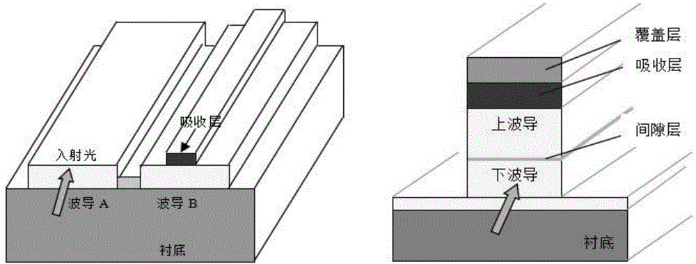
[0044] In the embodiment of the present invention, the working wavelength of the waveguide detector is 1.55 μm, the material of the substrate layer 1 is InP, the material of the waveguide layer 2 is InGaAsP, the material of the absorption layer 3 is InGaAs, and the material of the cover layer 4 is InP.

[0045] First, some basic theoretical parameters are listed. The refractive index of the material used in the waveguide detector is shown in Table 1, and the thickness of each layer is shown in Table 2, wherein the widths of the left waveguide 21, the middle waveguide 22 and the right waveguide 23 are is 5 μm, and the total width of the waveguide layer 2 is 15 μm. The thickness of the covering transition layer 6 is 0.5 μm.

[0046] Table 1

[0047] waveguide material Refractive index InP 3.14 InGaAsP 3.3 InGaAs 3.56-0.1i

[0048] Table 2

[0049] layer waveguide layer Absorbent layer Overlay thickness 5μm 0.12μm 0....

Embodiment 2

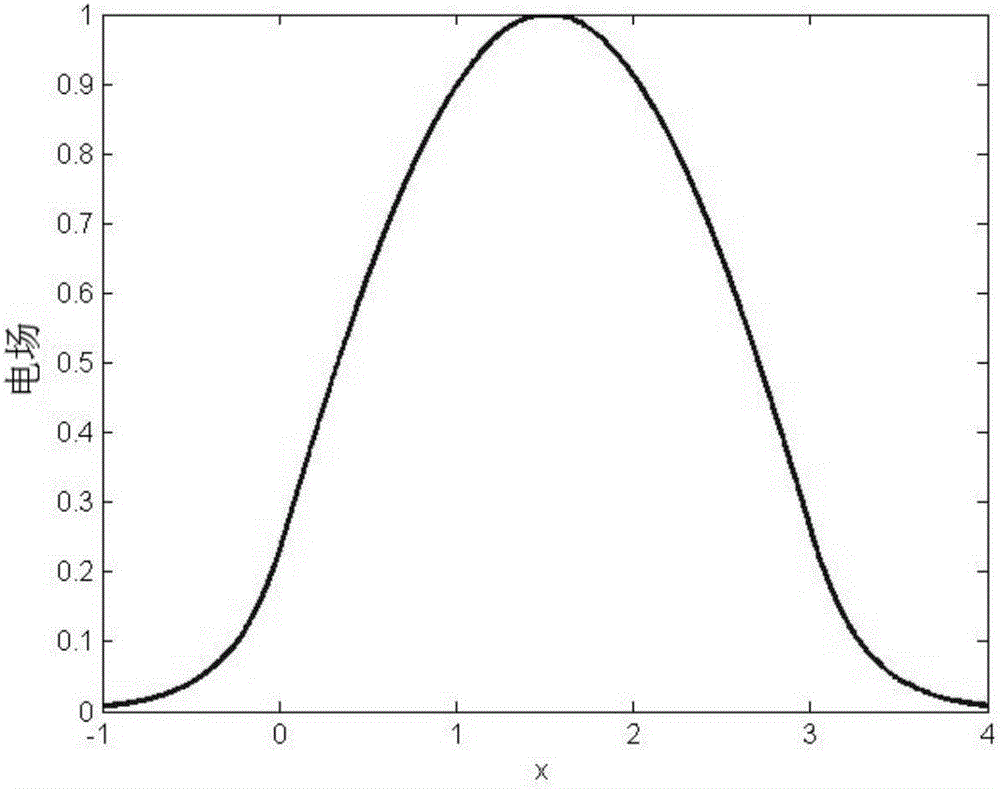
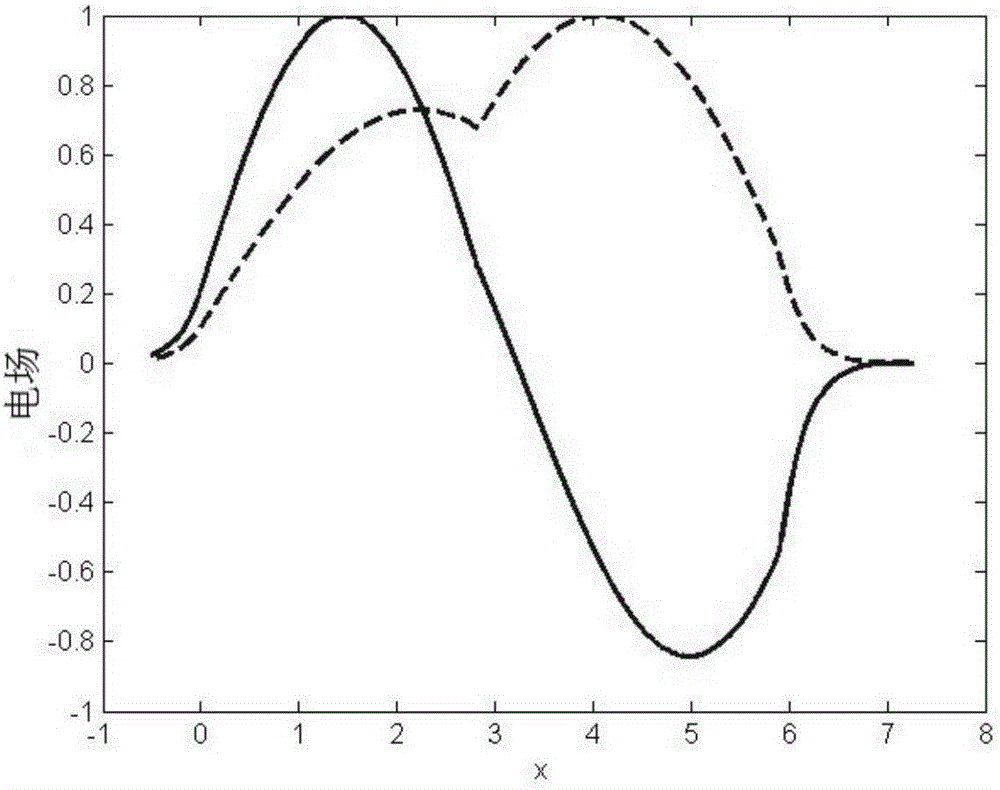
[0055] The above structural parameters are numerically simulated by using BeamPROP software, and the input light adopts Gaussian beam. For a horizontally symmetrical high-order supermode direction-coupled waveguide detector, the input light is irradiated on the end face in the middle of the waveguide layer 2 . The obtained waveguide refractive index distribution diagram and the simulation result diagram are as follows: Figure 8 and Figure 9 shown.

[0056] exist Figure 9 In the simulation result figure, the left box diagram represents the change of the optical field distribution along the z direction inside the horizontally symmetric high-order supermode direction-coupled waveguide detector. The block diagram on the right is the change diagram of optical power. When the waveguide length is 0, the first curve on the left is the change of the total power in the waveguide, the second curve is the change of power in the middle waveguide 22, and the third curve is the change ...


PUM


Abstract

The invention discloses a high-order supermode direction coupling waveguide detector with symmetric horizontal directions. The high-order supermode direction coupling waveguide detector sequentially comprises a substrate layer (1), a waveguide layer (2), an absorbing layer (3) and a covering layer (4) from bottom to top, wherein the waveguide layer (2) consists of a left waveguide (21), a middle waveguide (22) and a right waveguide (23) in parallel; the left waveguide (22) and the right waveguide (23) are of the same structure, and are symmetrically distributed. The high-order supermode direction coupling waveguide detector has the advantages that the problem of over-small incident light spot due to over-small cross section in the existing direction coupling waveguide detector, the vertical direction coupling waveguide detector and the symmetric structure type vertical direction coupling waveguide detector is solved; the diameter of the incident light spot is increased from 3 micrometers to 5 micrometers, so as to increase the photocurrent of the detector, and effectively improve the optical coupling efficiency from an optical fiber to waveguide.

Description

technical field [0001] The invention belongs to the field of optoelectronic technology, and in particular relates to the design of a horizontally symmetrical high-order supermode direction-coupled waveguide detector. Background technique [0002] The high-power high-speed photodetector is a detection device based on the interaction between light and matter, and its function is to convert the incident light signal into a high-power high-frequency signal. High-power high-speed optical detector is an indispensable device in optically controlled phased array radar, ultra-high-speed test system and optical fiber LAN communication, and its performance plays a decisive role in the whole system. [0003] Conventional vertical-incidence photodetectors cannot meet both high-speed and high-power requirements. The main reasons are as follows: one is the saturation effect, which limits the photocurrent; the other is the long transit time, which limits the response frequency; the third i...

Claims


Application Information

Patent Timeline
Patent Type & Authority Applications(China)
IPC IPC(8): G02B6/12
CPCG02B6/12G02B2006/12035G02B2006/12097G02B2006/12126G02B2006/12133
Inventor 余学才童文强李林松马朝阳
Owner UNIV OF ELECTRONICS SCI & TECH OF CHINA
Why Eureka
Try Eureka