
Ion implantation or implantation and deposition system

A deposition system and ion implantation technology, applied in the field of ion implantation or implantation and deposition systems, can solve the problems of limiting the application of ion implantation technology, unsatisfactory particle implantation quality, uneven implantation dose, etc., and achieve low cost, simple method, and isolation The effect of increasing the conversion rate

Active Publication Date: 2017-06-20
BEIHANG UNIV
View PDF5 Cites 0 Cited by
  • Summary
  • Abstract
  • Description
  • Claims
  • Application Information

AI Technical Summary

Problems solved by technology

However, when performing ion implantation on hard-to-ionized particles, due to the low ionization rate of the particles, the thickness of the ion sheath on the surface of the workpiece becomes larger. For non-spherical workpieces, the curvature of the sheath on the surface may generally be smaller than that of the workpiece itself. Curvature makes the implantation dose uneven in pores, slits, corners, edges, etc., resulting in unsatisfactory particle implantation quality, which severely limits the application of omni-directional ion implantation technology

Method used


Image

  • Ion implantation or implantation and deposition system
  • Ion implantation or implantation and deposition system
  • Ion implantation or implantation and deposition system

Examples


example 1

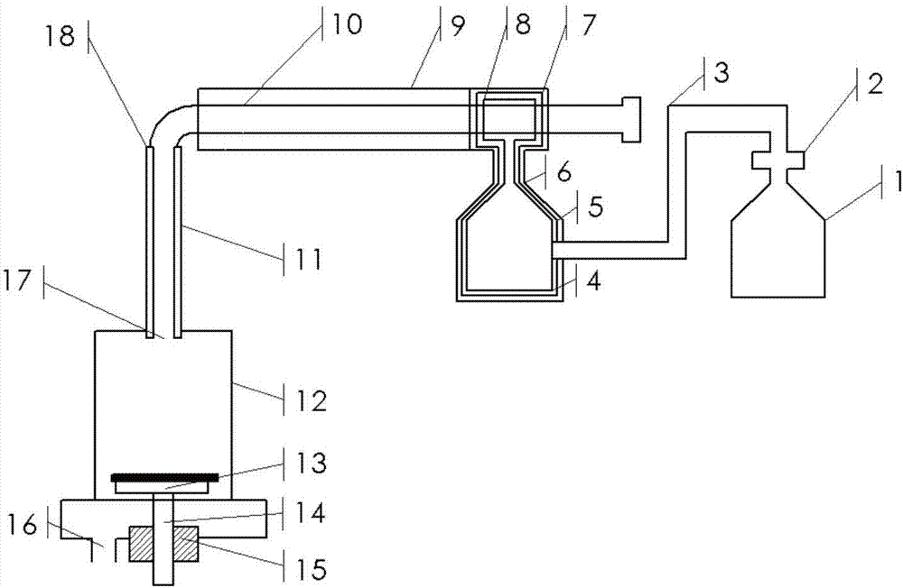
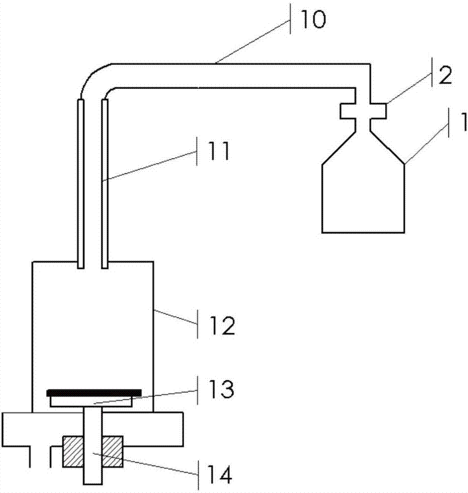
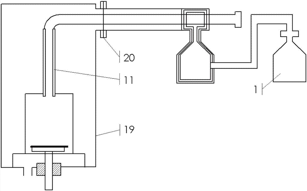
[0056] Example 1: In this embodiment, the aluminum oxide ceramic straight tube and the quartz glass straight tube with an inner diameter of 4 mm and a length of 200 mm are respectively selected as plasma-enhanced discharge devices, and hydrogen ions are implanted into the surface of single crystal silicon. Figure 4 device in .

[0057] Specific steps are as follows:

[0058] Step (1): An alumina ceramic straight tube and a quartz glass straight tube are respectively selected as plasma-enhanced discharge devices to build an ion implantation or implantation and deposition system. One end of the plasma-enhanced discharge device 11 is connected to the injection or injection and deposition studio 12 of the center opening of the end face. The injection or injection and deposition studio 12 is placed on the cathode target table 13. The mechanical pump and the molecular pump make the studio 12 When the vacuum state is reached, the gas is discharged through the exhaust port 16 of the...

example 2

[0066] Example 2: In this embodiment, an alumina ceramic straight tube and a quartz glass straight tube with an inner diameter of 4mm and a length of 200mm are respectively selected as the plasma enhanced discharge device, and oxygen ions are implanted on the surface of the single crystal silicon, and the Figure 4 device in . The difference between this embodiment and the first embodiment is: the oxygen flow rate is 10-60 sccm, and the oxygen ion implantation to the surface of the single crystal silicon is completed. Other steps are the same as Example 1.

[0067] The result is as Image 6 As shown, the average current in the figure is the injection current of oxygen ions. The more oxygen ions are injected, the greater the current, so the magnitude of the current can represent the ionization rate of particles.

[0068] Depend on Image 6 It can be seen that the current of oxygen ions can be increased by using a plasma-enhanced discharge device under the same gas flow rate....


PUM

PropertyMeasurementUnit
sizeaaaaaaaaaa
lengthaaaaaaaaaa
lengthaaaaaaaaaa

Abstract

The invention discloses an ion implantation or implantation and deposition system. The ion implantation or implantation and deposition system comprises an implantation or implantation and deposition work room of which the interior is in a vacuum state during processing of workpieces, a cathode target table used for supporting the workpieces to be processed in the implantation or implantation and deposition work room, a particle feeding source used for supplying particles for the implantation or implantation and deposition work room, a particle feeding pipeline connected with the particle feeding source and used for feeding the particles to the implantation or implantation and deposition work room, and a plasma-enhanced discharging device, wherein the plasma-enhanced discharging device is an insulating tube which can send out second electrons when the inner wall of the insulating tube is in electron collision, one end of the plasma-enhanced discharging device is connected with the particle feeding pipeline, the other end of the plasma-enhanced discharging device is connected with the implantation or implantation and deposition work room, so that the particles can enter the implantation or implantation and deposition work room from the particle feeding pipeline through the insulating tube. According to the ion implantation or implantation and deposition system, the particle ionization rate can be effectively improved, and the implantation or implantation and deposition quality and efficiency can be improved.

Description

technical field [0001] The present invention relates to ion implantation or implantation and deposition systems. Background technique [0002] At present, ion implantation or implantation and deposition technology has been widely used in many fields such as surface modification of metal materials, surface modification of biopolymer materials, and integrated circuit preparation. The application of ion implantation on semiconductors is mainly in the preparation of silicon on insulator (Silicon on Insulator, SOI) material and trench doping. At present, the widely used and promising SOI preparation technologies mainly include SIMOX (Separation by Implanted Oxygen) technology and Smart Cut technology. [0003] SIMOX technology is a new type of semiconductor material that implants high-dose oxygen ions into single crystal silicon to form an isolation layer under high temperature conditions, and forms a three-layer structure of top silicon, buried quartz, and bulk silicon under ul...

Claims


Application Information

Patent Timeline
Patent Type & Authority Applications(China)
IPC IPC(8): C23C14/48
CPCC23C14/48
Inventor 李刘合谷佳宾许亿
Owner BEIHANG UNIV
Learn More