A Method Adapted to Carbon Dioxide Capture and Power Generation in Cement Kiln Flue Gas

A carbon dioxide and cement kiln technology, applied in chemical instruments and methods, separation methods, cement production, etc., can solve problems such as inappropriate

Active Publication Date: 2019-07-30
长沙紫宸科技开发有限公司
View PDF3 Cites 0 Cited by
  • Summary
  • Abstract
  • Description
  • Claims
  • Application Information

AI Technical Summary

Problems solved by technology

Obviously, the existing CO 2 Cycle power generation technology is not suitable for the cement industry in my country

Method used


Image

  • A Method Adapted to Carbon Dioxide Capture and Power Generation in Cement Kiln Flue Gas
  • A Method Adapted to Carbon Dioxide Capture and Power Generation in Cement Kiln Flue Gas
  • A Method Adapted to Carbon Dioxide Capture and Power Generation in Cement Kiln Flue Gas

Examples


Embodiment 1

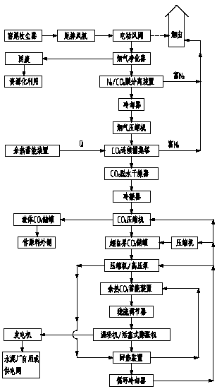
[0079] refer to figure 2 , one containing 2 sets of CO 2 Parallel capture of CO with continuous capture towers 2 , 2 sets of CO 2 A method for generating energy by an energy storage device mainly includes the following steps:

[0080] (1) Flue gas purification

[0081] An electric air valve is installed on the flue gas pipeline between the exhaust fan and the chimney after the dust collector at the end of the kiln in the cement plant to switch the direction of the flue gas, and the flue gas is continuously sent into the flue gas purifier by the power of the tail exhaust fan , using known methods such as "foam method / film bubble method / oxidation method" to purify harmful gaseous and dust pollutants in the flue gas and dehydrate them, the purified flue gas is continuously discharged from the gas outlet of the flue gas purifier, the flue gas purification process The solid waste generated in the process is discharged from the bottom of the flue gas purifier and utilized as a ...

Embodiment 2

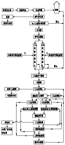
[0096] refer to image 3 , one containing 2 sets of CO 2 Continuous capture towers capture CO in series 2 , 2 sets of CO 2 A method for generating energy by an energy storage device mainly includes the following steps:

[0097] (1) Flue gas purification

[0098] An electric air valve is installed on the flue gas pipeline between the exhaust fan and the chimney after the dust collector at the end of the kiln in the cement plant to switch the direction of the flue gas, and the flue gas is continuously sent into the flue gas purifier by the power of the tail exhaust fan , using known methods such as "foam method / film bubble method / oxidation method" to purify harmful gaseous and dust pollutants in the flue gas and dehydrate them, the purified flue gas is continuously discharged from the gas outlet of the flue gas purifier, the flue gas purification process The solid waste (solid waste) generated in the process is discharged from the bottom of the flue gas purifier and utilized...

Embodiment 3

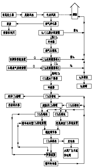
[0113] refer to Figure 4 , the dust content of flue gas from the kiln tail dust collector of the cement plant is 10mg / Nm 3 And when there are no harmful pollutants such as heavy metals, one contains 2 sets of CO 2 Continuous capture towers capture CO in series 2 , 2 sets of CO 2 A method for generating energy by an energy storage device mainly includes the following steps:

[0114] (1) CO 2 connection capture

[0115] CO with two sets in series 2 Continuous capture tower A and CO 2 Continuous capture column B to increase captured CO 2 purity;

[0116] An electric air valve is installed on the flue gas pipeline between the exhaust fan and the chimney after the dust collector at the end of the kiln in the cement factory. Cooling and flue gas compressor compression, continuously fed into the first set of CO set in series 2 Continuous capture tower A, CO 2 N-rich continuously discharged from the continuous capture tower A 2 The gas is directly evacuated through the ne...


PUM


Abstract

A method suitable for carbon dioxide capture and power generation in cement kiln flue gas, mainly including the following steps: (1) flue gas purification; (2) membrane separation and enrichment of CO 2 ; (3) CO 2 continuous capture; (4) CO 2 liquefaction storage; (5) supercritical CO 2 Fluid energy storage; (6) Supercritical CO 2 conditioning and power generation; (7) Supercritical CO 2 Recycling and heat recovery. The invention aims at the characteristics of the process equipment of the cement production line and the characteristics of the flue gas components, and uses the waste heat energy generated in the cement production process and / or the high-temperature heat energy that causes adverse effects as the main energy source to realize carbon dioxide capture and supercritical CO 2 Power generation has the advantages of low self-consumption, low investment, and low operating costs.

Description

technical field [0001] The invention relates to the field of low-carbon and energy technologies, and in particular to a carbon dioxide capture system that uses waste heat energy generated during cement production and / or high-temperature heat energy that causes adverse effects as the main energy source, aiming at the characteristics of cement production line process equipment and flue gas components. method of collection and generation. Background technique [0002] Climate change has become one of the issues affecting human survival and development, and industrial emissions of carbon dioxide are considered to be the main cause of climate warming. my country, as the largest developing country in the world, uses coal as its primary energy and fire The secondary energy structure dominated by power generation, with the rapid growth of economic aggregate, the CO of primary energy and secondary energy 2 Emissions are characterized by rapid growth and large total volume. However, t...

Claims


Application Information

Patent Timeline
Patent Type & Authority Patents(China)
IPC IPC(8): B01D53/78B01D53/22B01D47/06F27D17/00F01K7/32F01K17/04F01D15/10
CPCB01D47/06B01D53/228B01D53/78B01D2256/10B01D2257/2064B01D2257/2066B01D2257/302B01D2257/40B01D2257/504B01D2257/60B01D2257/70B01D2258/0233B01D2258/0283F01D15/10F01K7/32F01K17/04F27D17/004F27D2017/007Y02C20/40Y02E20/14Y02P10/25Y02P40/121Y02P70/10
Inventor 尹小林
Owner 长沙紫宸科技开发有限公司
Why Eureka
Try Eureka