Ultra-high-performance concrete reinforced hollow slab bridge structure and reinforcement method thereof

A technology of concrete reinforcement and hollow slab girder, applied in the direction of bridge reinforcement, bridges, bridge parts, etc., can solve the problems of constant traffic, damage of hinge joints, long repair time, etc., to reduce the impact of traffic, good construction performance, adhesion Good junction performance

Pending Publication Date: 2017-08-25
浙江宏日泰耐克新材料科技有限公司
View PDF5 Cites 7 Cited by
  • Summary
  • Abstract
  • Description
  • Claims
  • Application Information

AI Technical Summary

Problems solved by technology

[0002] Hollow slab girder bridge is a widely used bridge form in highway system. Due to unreasonable design and difficulty in guaranteeing construction quality, it is prone to damage of hinge joints between slabs, failure of lateral load transmission, and single slab Cases subject to heavy vehicle loads
[0003] Chinese patent CN 204475177 U discloses a bridge deck reinforcement pavement layer of lightweight concrete, which uses a lightweight concrete layer to replace the original concrete deck pavement layer in a hollow hinged slab bridge. Reinforcement mesh is arranged on the upper surface and the lower surface to improve the lateral stiffness and durability of the hollow hinged slab girder bridge. However, for the completed hollow slab girder bridge that only needs to be repaired and reinforced, it is neces...

Method used


Image

  • Ultra-high-performance concrete reinforced hollow slab bridge structure and reinforcement method thereof
  • Ultra-high-performance concrete reinforced hollow slab bridge structure and reinforcement method thereof

Examples


Embodiment 1

[0036] This example is the preparation process of the ultra-high performance concrete used in the present invention.

[0037] Concrete per cubic meter is composed of the following raw materials: cement 800-1200kg, mineral admixture 50-200kg, fine aggregate 800-1200kg, steel fiber 78-300kg, water reducer (solid content) 3-15kg, defoamer 0.6-5kg, expansion agent 60-120kg, water 105-250kg.

[0038] In a specific operation process, each cubic ultra-high performance concrete includes the following raw materials and quality: 950kg of Portland cement with a strength grade above 42.5; active SiO2 100kg; CaO 38kg; SO3 44.4kg; Al2O3 7.6kg; river sand 500kg; limestone Aggregate 200kg; slag fine aggregate 400kg; steel fiber 175kg; polycarboxylate superplasticizer 8kg; nonionic surfactant 3.5kg; magnesium oxide expansion agent 75kg; water 200kg.

[0039] Among them, the length of the steel fiber is 15-20 mm, the diameter is 0.15-0.25 mm, and the particle size of the river sand, limestone ...

Embodiment 2

[0043] This embodiment is a hollow slab girder bridge structure reinforced by the ultra-high performance concrete described in Embodiment 1.

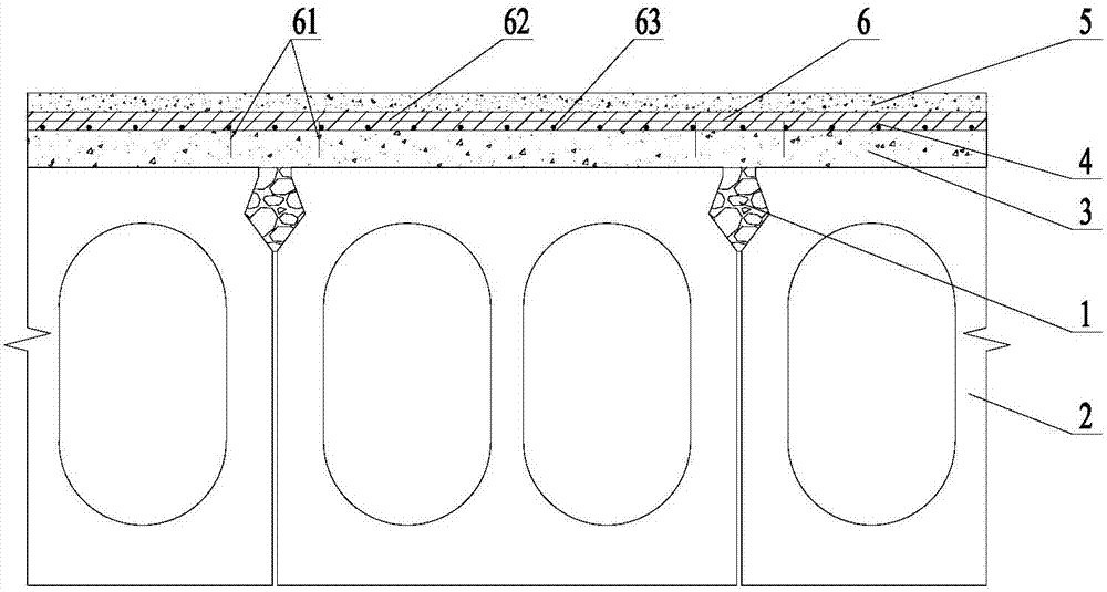
[0044] Such as figure 1 As shown, the ultra-high-performance concrete reinforced hollow slab girder bridge structure of the present invention includes hollow slab girders 2 connected side by side by hinge joints 1 and a bridge deck pavement layer laid on the top of the hollow slab girder 2. The deck pavement layer from bottom to top is an ordinary concrete layer 3, an ultra-high performance concrete reinforcement layer 4 and an asphalt concrete layer 5; wherein, the ultra-high performance concrete reinforcement layer 4 is internally provided with a steel structure 6 connected to the ordinary concrete layer , in order to improve the bearing capacity of the reinforced hollow slab girder bridge.

[0045] In this embodiment, the thickness of the ordinary concrete layer 3 is 8 cm, the thickness of the reinforced ultra-high performance concret...

Embodiment 3

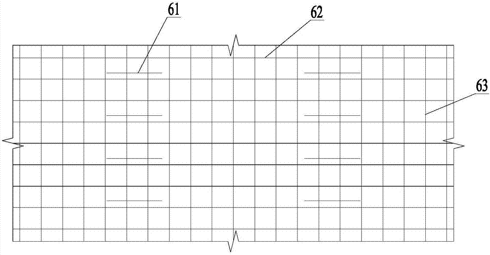
[0051] This embodiment is the reinforcement method of the hollow slab girder bridge structure reinforced by ultra-high performance concrete described in Embodiment 2. Its specific steps are as follows: during construction, the previously laid asphalt concrete layer (about 6 ~ 10mm) to expose the ordinary concrete layer; along both sides of the hinge joint, insert steel bars on the ordinary concrete layer; clean up the ordinary concrete layer (no special treatment such as chiseling) and lay reinforcement mesh, the reinforcement mesh includes a layer Horizontal steel and a layer of longitudinal steel bars; then pour a thin layer of ultra-high performance concrete on the ordinary concrete layer, and bury the implanted steel bars and steel mesh in it to form an ultra-high performance concrete reinforcement layer (about 3-5mm); the pouring is completed Afterwards, the ultra-high-performance concrete reinforcement layer is cured at room temperature for 2 hours, and then the asphalt c...


PUM

PropertyMeasurementUnit
Thicknessaaaaaaaaaa
Thicknessaaaaaaaaaa
Diameteraaaaaaaaaa

Abstract

The invention relates to an ultra-high-performance concrete reinforced hollow slab bridge structure. The ultra-high-performance concrete reinforced hollow slab bridge structure comprises hollow plate beams connected through hinge joints side by side as well as a bridge deck pavement layer above the hollow plate beams, wherein the bridge deck pavement layer comprises an ordinary concrete layer, an ultra-high-performance concrete reinforcement layer and an asphalt concrete layer; a steel reinforcement structure connected with the ordinary concrete layer is arranged in the ultra-high-performance concrete reinforcement layer. The invention further relates to a reinforcement method of the hollow slab bridge structure. The method comprises steps as follows: an original concrete layer is chiseled away; steel reinforcements are inlaid and implanted into the ordinary concrete layer, and a steel reinforcement net is paved; thin-layer ultra-high-performance concrete is poured and cured at the normal temperature, and an asphalt concrete layer is spread. Compared with the prior art, the hollow slab bridge structure and the reinforcement method have the characteristics of simple construction conditions and high construction speed, interference and influences of a conventional bridge reinforcement scheme on traffic are reduced, and better economy is realized; because of the high durability and normal-temperature curing characteristics of ultra-high-performance concrete, the service life of the hollow slab bridge structure is longer, and the curing cost is effectively reduced.

Description

technical field [0001] The invention relates to the technical field of bridge reinforcement, in particular to a hollow slab girder bridge structure reinforced with ultra-high performance concrete and a reinforcement method thereof. Background technique [0002] Hollow slab girder bridge is a widely used bridge form in highway system. Due to unreasonable design and difficulty in guaranteeing construction quality, it is prone to damage of hinge joints between slabs, failure of lateral load transmission, and single slab Cases with heavy vehicle loads. [0003] Chinese patent CN 204475177 U discloses a bridge deck reinforcement pavement layer of lightweight concrete, which uses a lightweight concrete layer to replace the original concrete deck pavement layer in a hollow hinged slab bridge. Reinforcement mesh is arranged on the upper surface and the lower surface to improve the lateral stiffness and durability of the hollow hinged slab girder bridge. However, for the completed h...

Claims


Application Information

Patent Timeline
IPC IPC(8): E01D22/00E01D19/08
CPCE01D19/083E01D22/00
Inventor 刘超刘国平王俊颜赵正
Owner 浙江宏日泰耐克新材料科技有限公司
Why Eureka
Try Eureka