Ultrahigh-performance concrete reinforced channel girder deck structure and reinforcing method thereof

A concrete reinforcement and ultra-high performance technology, which is applied in bridge reinforcement, bridge, bridge construction, etc., can solve the problems of long curing time in high temperature steam, difficulty in guaranteeing durability, and inconvenient transportation, so as to ensure durability and increase the rigidity of the whole section , the effect of preventing shedding

Pending Publication Date: 2017-09-12
浙江宏日泰耐克新材料科技有限公司
View PDF7 Cites 1 Cited by
  • Summary
  • Abstract
  • Description
  • Claims
  • Application Information

AI Technical Summary

Problems solved by technology

In the common reinforced concrete injection molding reinforcement method, the effect is better to use ultra-high performance concrete, but the current ultra-high performance concrete requires high-temperature steam curing, which can make its excessive shrinkage and creep be eliminated as much as possible during the curing stage. , to ensure that ultra-high performance concrete will not produce large cracks due to shrinkage and creep in subsequent use, but its high-temperature steam curing time is long and the construction is cumbersome, and its curing time is not less than 48 hours
The above reinforcement methods all need to close the traffic, which causes great inconvenience to the traffic, and the reinforced structure needs good maintenance, and the durability is difficult to guarantee

Method used


Image

  • Ultrahigh-performance concrete reinforced channel girder deck structure and reinforcing method thereof
  • Ultrahigh-performance concrete reinforced channel girder deck structure and reinforcing method thereof
  • Ultrahigh-performance concrete reinforced channel girder deck structure and reinforcing method thereof

Examples


Embodiment 1

[0039] This example is the preparation process of the ultra-high performance concrete used in the present invention.

[0040] Concrete per cubic meter is composed of the following raw materials: cement 800-1200kg, mineral admixture 50-200kg, fine aggregate 800-1200kg, steel fiber 78-300kg, water reducer (solid content) 3-15kg, defoamer 0.6-5kg, expansion agent 60-120kg, water 105-250kg.

[0041] In a specific operation process, each cubic ultra-high performance concrete includes the following raw materials and quality: Portland cement 765kg; active SiO 2 72kg; CaO48kg; SO 3 22.5kg; Al 2 o 3 7.5kg; quartz sand 300kg; river sand 300kg; slag 400kg; steel fiber 128kg; naphthalene superplasticizer 9kg; silicone defoamer 2kg; calcium oxide expansion agent 75kg; water 200kg.

[0042] Among them, the length of steel fiber is 15-20mm, the diameter is 0.15-0.25mm, and the particle size of quartz sand, river sand and slag is all less than or equal to 5mm.

[0043] The ultra-high pe...

Embodiment 2

[0046] This embodiment is a channel beam bridge deck structure reinforced by the ultra-high performance concrete prepared in Embodiment 1.

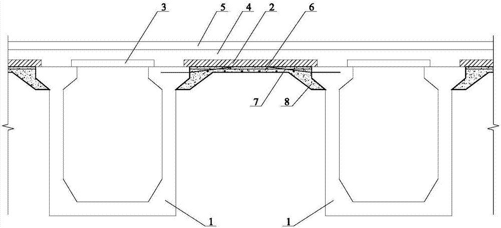
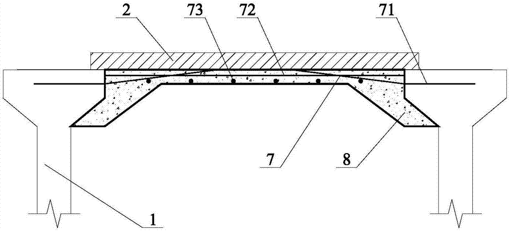
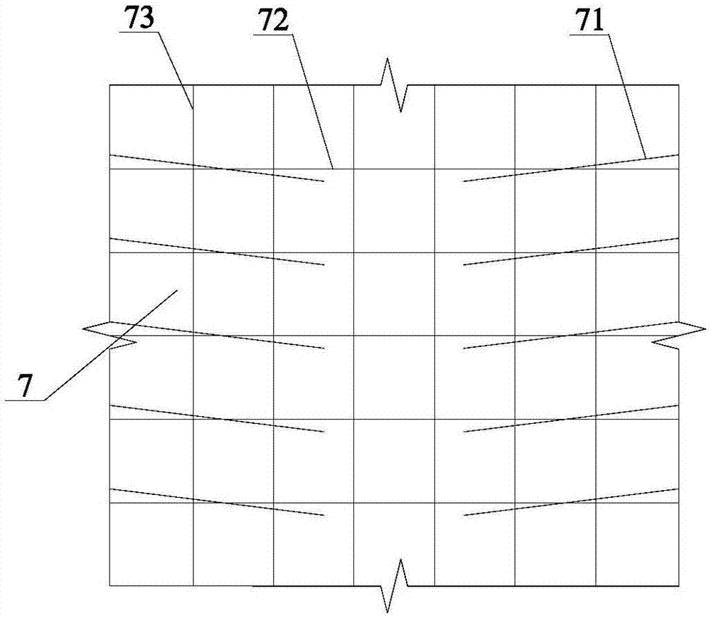
[0047] Such as figure 1 As shown, the ultra-high performance concrete reinforced channel beam deck structure of the present invention includes channel beams 1, a bridge deck 2 erected between the channel beams 1, and a bridge deck erected above the channel beams 1. Type B bridge deck 3 and the concrete pavement layer 4 and asphalt layer 5 laid on the top of the Type A bridge deck 2 and the Type B bridge deck 3, which also includes an ultra-high performance concrete reinforcement layer at the bottom of the Type A bridge deck 2 6; the ultra-high-performance concrete reinforcement layer 6 includes a steel bar structure 7 connected to the channel beam 1 and an ultra-high-performance concrete layer 8 cast in the steel bar structure 7, and the side shape of the ultra-high-performance concrete reinforcement layer 6 It is π-shaped with thicker s...

Embodiment 3

[0053] This embodiment is the reinforcement method of the channel beam bridge deck structure reinforced by ultra-high performance concrete described in Embodiment 2. The specific steps are as follows: during construction, the original concrete layer at the bottom of the A-type bridge deck is first surface-treated to remove the A-type bridge deck. For the broken and loose concrete on the surface of the Type A bridge deck, after the surface treatment, the debris and powder are thoroughly washed, and the thickness of the removed original concrete layer is about 2-5cm; For rust treatment, first use a wire brush, sand plate, sackcloth, etc. to gently wipe off the rust, and then use a steel bar rust remover to dissolve and remove the rust; The depth of the inserted steel bar in the channel beam is 18 times or 20 times the diameter of the implanted steel bar; use the implanted steel bar to erect the steel mesh, and weld or bind the thin steel bars between the steel bars; The formwork...


PUM


Abstract

The invention relates to an ultrahigh-performance concrete reinforced channel girder deck structure. The ultrahigh-performance concrete reinforced channel girder deck structure comprises channel girders, an A-type deck slab and an ultrahigh-performance concrete reinforcing layer positioned at the bottom of the A-type deck slab, wherein the ultrahigh-performance concrete reinforcing layer comprises a rebar structure connected with the channel girders and an ultrahigh-performance concrete layer poured into the rebar structure. The invention further relates to a reinforcing method of the channel girder deck structure, and the reinforcing method comprises the following steps: corresponding treatment is performed on the bottom of the A-type deck slab; implanted rebars are embedded into the channel girders, and a bar-mat reinforcement is built on the channel girders; a template is adopted for formwork supporting to pour ultrahigh-performance concrete; and normal-temperature maintenance is performed on ultrahigh-performance concrete, and the template is detached. The construction conditions are simple, the construction speed is high, interference and impacts on the traffic from a traditional bridge reinforcing scheme are reduced, the ultimate bearing capacity of original channel girders is greatly improved, good economical efficiency is achieved, and as ultrahigh-performance concrete has high durability and normal-temperature curing characteristic, the service life is longer, and the maintenance cost is lowered.

Description

technical field [0001] The invention relates to the technical field of bridge reinforcement, in particular to a channel beam deck structure reinforced by ultra-high performance concrete and a reinforcement method thereof. Background technique [0002] As a bridge form widely used in highway system, trough girder bridge is prone to roof and floor cracks, steel bar corrosion and other diseases due to unreasonable design and difficulty in guaranteeing construction quality. The prefabricated armor plate built between the channel beams is difficult to ensure the overall force, so the armor plate is prone to cracks or falling damage. [0003] The currently used reinforcement methods mainly include reinforced concrete mold injection reinforcement method, steel plate or steel reinforcement method, and fiber material reinforcement method. In the common reinforced concrete injection molding reinforcement method, the effect is better to use ultra-high performance concrete, but the cur...

Claims


Application Information

Patent Timeline
Patent Type & Authority Applications(China)
IPC IPC(8): E01D22/00E01D19/08
CPCE01D19/083E01D22/00
Inventor 刘超刘国平王俊颜赵正
Owner 浙江宏日泰耐克新材料科技有限公司
Why Eureka
Try Eureka