A low-grade copper oxide ore heap leaching and dripping process

A copper oxide ore, low-grade technology, applied in the direction of photography technology, photography auxiliary technology, process efficiency improvement, etc., can solve the problems of unbalanced leaching and recovery of raw ore, poor management and control, hindering the penetration of leaching liquid, etc., to improve leaching. Speed ​​and leaching rate, simple laying, beneficial effect on recovery rate

Active Publication Date: 2018-11-13
云南省核工业二0九地质大队
View PDF5 Cites 0 Cited by
  • Summary
  • Abstract
  • Description
  • Claims
  • Application Information

AI Technical Summary

Problems solved by technology

In order to fully contact the chemical solvent with metal copper ions, most mines currently adopt the heap leaching and spraying method. The spraying process is used for heap leaching. First, the acid-containing solution is sprayed into the air and is easy to atomize and spread, which will harm human health. It has a certain impact on the environment; secondly, the management and control during the operation process is not easy to grasp, and the loss of acid and water is relatively large; thirdly, during the spraying process, the spraying solution will have an impact on the silty ore, and to a certain extent will form Hardening hinders the infiltration of the leachate, and water accumulates on the surface of the ore heap, which is easy to form runoff. The solution is easily segregated in the heap, and the leaching efficiency is reduced. The production cycle is long, the leaching rate is low, and improper management and control will cause the slope of the ore heap to collapse or partially collapse

Method used


Image

  • A low-grade copper oxide ore heap leaching and dripping process
  • A low-grade copper oxide ore heap leaching and dripping process
  • A low-grade copper oxide ore heap leaching and dripping process

Examples


Embodiment 1

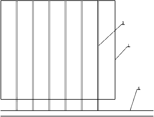
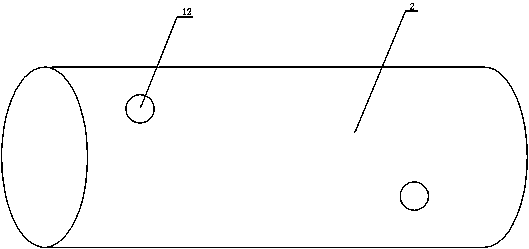
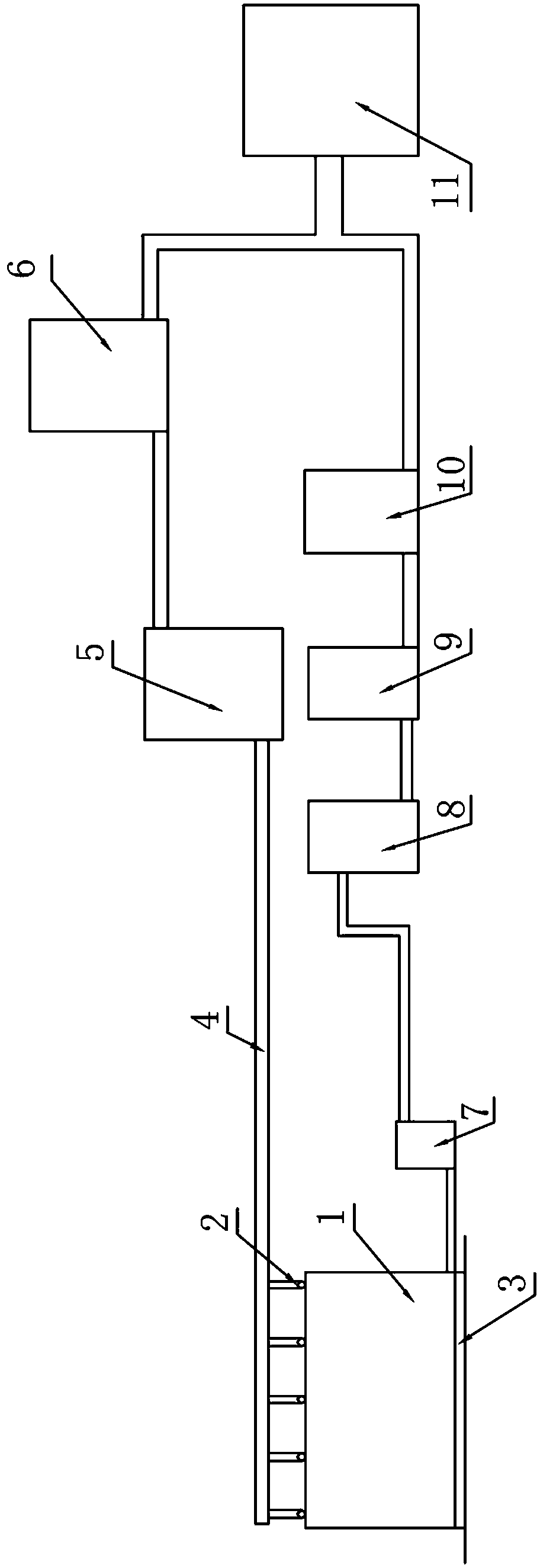
[0039] see figure 1 , figure 2 , image 3, a structural diagram of a heap leaching and dripping device for low-grade copper oxide ore, a partial structural diagram of a heap leaching and dripping device for low-grade copper oxide ore, and another part of a heap leaching and dripping device for low-grade copper oxide ore Structural schematic diagram, a heap leaching and dripping device for low-grade copper oxide ore, including dripping pipeline 2, anti-leakage pad 3, delivery pipe 4, filter 5, high-level adjustment pool 6, collection pool 7, rich solution pool 8, Extraction electrowinning device 9, barren solution pool 10 and sulfuric acid storage tank 11, said dripping pipeline 2 is laid on the surface of ore heap 1, and an anti-leakage pad 3 is arranged between said ore heap 1 and the ground, said dripping The shower pipe 2 is communicated with the conveying pipe 4, and the conveying pipe 4 is provided with twenty dripping pipes 2, and the conveying pipe 4 is communicated ...

Embodiment 2

[0050] see figure 1 , figure 2 , image 3 , a structural diagram of a heap leaching and dripping device for low-grade copper oxide ore, a partial structural diagram of a heap leaching and dripping device for low-grade copper oxide ore, and another part of a heap leaching and dripping device for low-grade copper oxide ore Structural schematic diagram, a heap leaching and dripping device for low-grade copper oxide ore, including dripping pipeline 2, anti-leakage pad 3, delivery pipe 4, filter 5, high-level adjustment pool 6, collection pool 7, rich solution pool 8, Extraction electrowinning device 9, barren solution pool 10 and sulfuric acid storage tank 11, said dripping pipeline 2 is laid on the surface of ore heap 1, and an anti-leakage pad 3 is arranged between said ore heap 1 and the ground, said dripping The shower pipe 2 is communicated with the conveying pipe 4, and the conveying pipe 4 is provided with twenty-five dripping pipes 2, and the conveying pipe 4 is communi...

Embodiment 3

[0061] see figure 1 , figure 2 , image 3 , a structural diagram of a heap leaching and dripping device for low-grade copper oxide ore, a partial structural diagram of a heap leaching and dripping device for low-grade copper oxide ore, and another part of a heap leaching and dripping device for low-grade copper oxide ore Structural schematic diagram, a heap leaching and dripping device for low-grade copper oxide ore, including dripping pipeline 2, anti-leakage pad 3, delivery pipe 4, filter 5, high-level adjustment pool 6, collection pool 7, rich solution pool 8, Extraction electrowinning device 9, barren solution pool 10 and sulfuric acid storage tank 11, said dripping pipeline 2 is laid on the surface of ore heap 1, and an anti-leakage pad 3 is arranged between said ore heap 1 and the ground, said dripping The shower pipe 2 is communicated with the conveying pipe 4, and the conveying pipe 4 is provided with fifteen dripping pipes 2, and the conveying pipe 4 is communicate...


PUM


Abstract

The invention discloses a heap leaching dripping technique for low-grade copper oxide ore. The heap leaching dripping technique includes the following steps that prescreening is conducted; a sieve material is crushed; heap construction is performed; drop-leaching pipelines are laid; dilute sulphuric acid is prepared; drop-leaching operation is executed, and the dilute sulphuric acid is evenly dipped onto the surface layer of a stock heap; rich liquor recovery is performed, copper in copper mineral exists in dripping liquor in the mode of ions and is further gathered in a gathering tank on the downstream of the stock heap, and the gathered rich liquor is pumped into a rich liquor pond through a conveying pump; and extraction electrodeposition is carried out, the rich liquor is subjected to extraction and electrodeposition through an extraction electrodeposition device, and accordingly copper metal is obtained. According to the heap leaching dripping technique, the dripping method is adopted to conduct heap leaching on original copper ore, an acid solution acts on the ore surface directly, no ponding layer can be formed on the surface of the stock heap by means of diffusion dialysis, the phenomena of stock heap hardening and heap-in solution segregation are eliminated completely, and the permeating speed is high; and the acid solution can make full contact with the copper metal, which is beneficial to precipitation of the copper metal ions.

Description

technical field [0001] The invention belongs to the technical field of hydrometallurgy, and in particular relates to a heap leaching and dripping process of low-grade copper oxide ore. Background technique [0002] For the beneficiation and smelting of low-grade copper oxide ores, the heap leaching method has the advantages of simple process equipment, low investment, large scale and good benefits. It is an important means of hydrometallurgy to recover copper and has been widely used at home and abroad. In order to fully contact the chemical solvent with metal copper ions, most mines currently adopt the heap leaching and spraying method. The spraying process is used for heap leaching. First, the acid-containing solution is sprayed into the air and is easy to atomize and spread, which will harm human health. It has a certain impact on the environment; secondly, the management and control during the operation process is not easy to grasp, and the loss of acid and water is rela...

Claims


Application Information

Patent Timeline
Patent Type & Authority Patents(China)
IPC IPC(8): C22B15/00C25C1/12
CPCC22B15/0071C22B15/0084C25C1/12Y02P10/20
Inventor 李明晓刘凤祥王刚王学武李余华杨晓伟赵国兵张向东谭伟蒋国祥王宏锋杨庆超
Owner 云南省核工业二0九地质大队
Why Eureka
Try Eureka