Microwave drying method and device adopted by same

A microwave drying and drying technology, applied in the direction of drying gas arrangement, heating device, drying solid materials, etc., can solve the problems of hot air loss temperature, slow heating speed, large heat loss, etc., and achieve the goal of accelerating the drying process and raising the average temperature Effect

Pending Publication Date: 2017-11-03
湖南源创高科工业技术有限公司
View PDF7 Cites 9 Cited by
  • Summary
  • Abstract
  • Description
  • Claims
  • Application Information

AI Technical Summary

Problems solved by technology

The existing commercial microwave drying technology pays attention to the efficient heating effect of microwave on drying products, and ignores the surrounding low-temperature atmosphere when these materials are heated by microwaves. A large amount of heat energy from microwaves is transferred from materials to microwave drying through convection, radiation, conduction, etc. In the cold air in the cavity, the heating rate slows down and the microwave efficiency decreases
[0007] Secondly, the heat loss accompanying the existing microwave drying technology is too large
With the progress of the drying process, the air humidity in the microwave drying chamber gradually increases, and the temperature also gradually increases. The existing microwave drying process adopts the method of forced air extraction and dehumidification at regular intervals or when the humidity is higher than the threshold value, which carries a large amount of sensible heat and The hot and humid air with latent heat of water vapor is dehumidified and emptied, and the lost air is replenished externally. Although the purpose of dehumidification and water discharge can be achieved, the price is a large loss of hot air in the drying chamber and a sharp drop in temperature. The compensation for the lost heat will be directly Increase energy consumption and reduce the benefit of microwave drying process
[0008] Finally, the existing commercial microwave drying methods have not been able to connect with the original optimal drying process of materials, and cannot give full play to the characteristics of fast, efficient and efficient microwave drying. Changes can only be made by suppressing the contribution of microwave heating and reducing microwave input power. These will greatly reduce the efficiency of microwave drying and cannot "make the best use of everything".

Method used


Image

  • Microwave drying method and device adopted by same
  • Microwave drying method and device adopted by same
  • Microwave drying method and device adopted by same

Examples


Embodiment 1

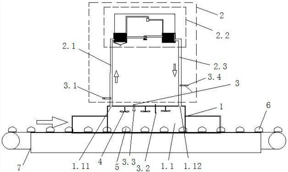
[0054] A microwave drying method (taking the drying of building blocks with a maximum size of 30mm as an example, with a moisture content of 21.5% to 2%), the device used is detailed in figure 1 , specifically including microwave drying equipment 1, a circulating air control system 2 that provides circulating hot air for the microwave drying equipment 1, a temperature sensor group 3 and an auxiliary circulation device 4, the details are as follows:

[0055] The microwave drying equipment 1 includes a sealed chamber 1.1 provided with an insulating layer, and the sealed chamber 1.1 is provided with an outlet 1.11 containing humid air and an inlet 1.12 for dehumidifying warm air.

[0056] The circulation control system 2 includes a wet air flow pipe 2.1, a processing part 2.2 for post-processing the wet air, and a dehumidified warm air flow pipe 2.3. The air outlet is connected, and the outlet end of the processing part is connected with the dehumidifying warm air inlet through t...

Embodiment 2

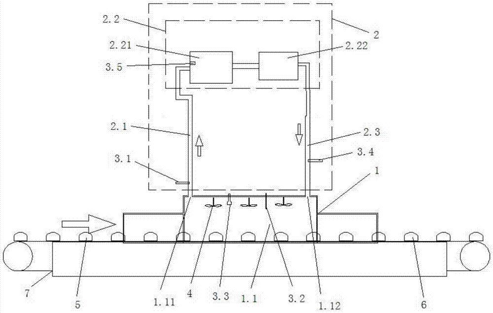
[0075] The specific scheme of this embodiment is detailed in image 3 and Figure 4 , which differs from Example 1 in the following two aspects:

[0076] The device structures are different, specifically: (1) the processing unit includes a condenser 2.21 and a heater 2.22, the condenser 2.21 is used for cooling and dehumidification of the humid wind, and the heater 2.22 is used for Carry out heat treatment to described dehumidification wind (heater can be the parts that can be heated such as heat exchanger, heat pump, when adopting heat pump, specifically: the cold end of heat pump is from atmosphere, industrial flue gas, natural water body, water body containing geothermal heat The heat is obtained from the heat pump and transferred to the hot end, and the hot end of the heat pump is used as a heater); the air inlet of the condenser is connected with the outlet of the wet air through the wet air flow pipe, and the air outlet of the condenser is connected with the The air in...


PUM


Abstract

The invention provides a microwave drying method. The microwave drying method comprises the following steps: placing a product to be dried in a sealing cavity of microwave drying equipment; performing microwave drying through the microwave drying equipment emitting microwaves and meanwhile performing forced convection on a gas in the sealing cavity; and monitoring the temperature of the gas in the sealing cavity and the surface temperature of the product to be dried, and at the same time performing post-treatment on the gas in the sealing cavity and enabling the gas after post-treatment to return to the sealing cavity in a cyclic manner. According to the microwave drying method and the device adopted by the same, the temperature and humidity of the gas medium in the sealing cavity are controlled on the basis of the conventional microwave drying technology, meanwhile the essence of the material drying principle is well utilized, so that the purpose of performing microwave drying by efficiently utilizing microwaves is achieved, and technological problems that materials are excessively dried, deformed, burned and denatured during the microwave drying process are effectively avoided; meanwhile, the microwave drying process is enhanced in an energy-saving manner through approaches such as complete moisture circulation and reutilization and cavity heat preservation. The invention further discloses the device adopted by the method, parts are easy to obtain, and the implementation is easy to realize.

Description

technical field [0001] The invention relates to the technical field of microwave drying, in particular to a microwave drying method and a device used therefor. Background technique [0002] The microwave drying method makes full use of the advantages of high microwave heating speed and high efficiency, greatly shortens the time required for drying products, and has a significant effect of energy saving and efficiency improvement. Microwave drying has been fully recognized in social production. [0003] Microwave drying is a method of internal heating, specifically: the wet material is placed in a microwave high-frequency electric field with a very short oscillation period, and the water molecules inside it will be polarized and arranged neatly along the direction of the microwave electric field, and then rapidly increase with the high temperature. Rotation due to alternating changes in the direction of the frequency alternating electric field, and violent collisions and fric...

Claims


Application Information

Patent Timeline
Patent Type & Authority Applications(China)
IPC IPC(8): F26B3/347F26B9/06F26B21/04F26B21/10F26B23/08F26B25/22
CPCF26B3/347F26B9/06F26B21/04F26B21/10F26B25/22
Inventor 彭虎夏广斌刘建平刘忠
Owner 湖南源创高科工业技术有限公司
Why Eureka
Try Eureka