
Industrial sludge, waste emulsion slag and metallurgical ash joint treatment system and power generation process thereof

A technology for industrial sludge and waste emulsion, which is applied in joint combustion mitigation, chemical instruments and methods, incinerators, etc., can solve the problem of low efficiency of boiler dusty waste gas treatment, pollution of soil, water quality, and easy generation of odor, etc. problem, to achieve the effect of stable properties, low viscosity and high heating efficiency

Active Publication Date: 2017-12-22
马钢集团设计研究院有限责任公司
View PDF4 Cites 2 Cited by
  • Summary
  • Abstract
  • Description
  • Claims
  • Application Information

AI Technical Summary

Problems solved by technology

[0011] Aiming at the problems in the prior art that when industrial sludge, waste emulsion slag and metallurgical ash are treated separately, soil and water quality are polluted, odors are easily generated, treatment costs are high, and boiler dusty waste gas treatment efficiency is low. The invention provides a combined treatment system for industrial sludge, waste emulsion slag and metallurgical ash and its power generation process

Method used


Image

  • Industrial sludge, waste emulsion slag and metallurgical ash joint treatment system and power generation process thereof
  • Industrial sludge, waste emulsion slag and metallurgical ash joint treatment system and power generation process thereof
  • Industrial sludge, waste emulsion slag and metallurgical ash joint treatment system and power generation process thereof

Examples


Embodiment 1

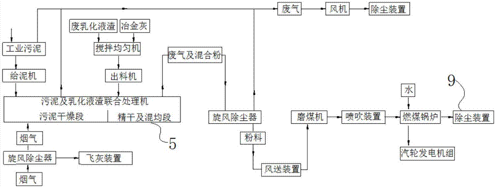
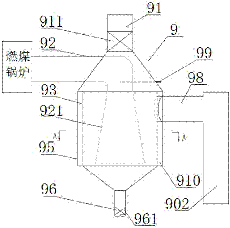
[0051] A combined treatment system for industrial sludge, waste emulsion slag and metallurgical ash in this embodiment, such as figure 1 As shown, it includes a mud feeder, a mixer, a discharger, an air delivery device, a coal mill, an injection device, a coal-fired boiler and a steam turbine generator set, and also includes a sludge and emulsified liquid slag joint processor 5 and Dust removal device 9, such as figure 2 As shown, the sludge and emulsified liquid slag joint processor 5 has a horizontal barrel-like structure as a whole, including a drive shaft 59 that runs through the center line of the barrel body. A scraper spiral agitator is fixedly connected around the shaft 59, and the barrel body is provided with a sludge inlet 53, a high-temperature flue gas inlet 52, an emulsion slag inlet 56 and a discharge outlet 58, wherein: the sludge feeder transfers industrial sludge The high-temperature flue gas for heating is passed into the barrel through the high-temperature...

Embodiment 2

[0054] A combined treatment system for industrial sludge, waste emulsion slag and metallurgical ash in this embodiment has the same basic structure as in Embodiment 1, the difference and improvement are: it also includes two cyclone dust collectors, which are respectively cyclone dust collector one and Cyclone dust collector 2; cyclone dust collector 1 is installed at the high-temperature flue gas inlet 52. The high-temperature flue gas for heating is first processed by the cyclone dust collector and then passed into the barrel. The high-temperature flue gas after dust removal directly contacts the material to avoid dust. interference, high heating efficiency; the second cyclone dust collector is arranged at the discharge outlet 58, and the waste gas and the mixture discharged from the discharge outlet 58 pass through the powder treated by the second cyclone dust collector and then communicate with the air delivery device through the pipeline, and the waste gas and the mixture ...

Embodiment 3

[0064] A combined treatment system for industrial sludge, waste emulsion slag and metallurgical ash in this embodiment has the same basic structure as in Embodiment 2, the difference and improvement is that the industrial sludge is temporarily stored in a sealed industrial sludge storage The odor of the sludge storage, the sludge and emulsion slag joint processor 5 and the waste gas of the cyclone dust collector 2 are all passed through the pipeline into the dust removal device 9 for treatment and then discharged into the atmosphere; the sludge and emulsion slag joint processor 5 Negative pressure inside to avoid leakage of odor and pollute the environment. The sludge and emulsified liquid slag joint processor 5 is divided into two sections, the front section is the sludge drying section, the rear section is the fine drying and mixing section, and a swirl plate 55 is arranged between the two sections, and the scraper screw agitator in the front section is the coarse Toothed sc...


PUM


Abstract

The invention discloses an industrial sludge, waste emulsion slag and metallurgical ash joint treatment system and a power generation process thereof, and belongs to the technical field of dangerous waste comprehensive treatment and heat energy utilization. The joint treatment system comprises a sludge feeding machine, a uniform stirring machine, a discharging machine, an air supply device, a coal mill, a blowing device, a coal-fired boiler, a steam turbine generator unit, a sludge and emulsion slag joint treatment machine and a dust removal device. The sludge and emulsion slag joint treatment machine is wholly of a horizontal bucket structure and comprises a drive shaft penetrating the center line of a bucket body, the two ends of the drive shaft are in transmission connection with an electric motor, the periphery of the drive shaft is fixedly connected with a scraper spiral stirrer, and a sludge inlet, a high-temperature smoke inlet, an emulsion slag inlet and a discharging outlet are formed in the bucket body. The problems that in the prior art, when industrial sludge, waste emulsion slag and metallurgical ash are independently treated, soil and water are polluted, bad smells are easily generated, treatment cost is high, and the boiler dust-containing waste smoke is low in treatment efficiency are solved.

Description

technical field [0001] The invention relates to the technical field of comprehensive treatment of hazardous waste and utilization of heat energy, in particular to a combined treatment system for industrial sludge, waste emulsion slag and metallurgical ash and a power generation process. Background technique [0002] There are industrial sewage treatment stations in the existing metallurgical complexes. While using water in production, a large amount of industrial sludge is produced. The sludge has a high moisture content, and the sludge has a strong odor and emits harmful gases. The mud contains heavy metals such as lead, cadmium, mercury, and chromium. Currently, there is no good disposal method. Generally, direct landfilling is used, which will occupy land for a long time and have a negative impact on the soil, water quality and environment in the landfill area. [0003] However, the steel rolling process in metallurgical production requires an emulsion. Long-term use of t...

Claims


Application Information

Patent Timeline
Patent Type & Authority Applications(China)
IPC IPC(8): F23G5/02F23G5/44F23G5/46F23J15/02B01D50/00
CPCB01D50/00F23G5/02F23G5/444F23G5/46F23J15/027Y02E20/12
Inventor 王皖吴庆非邓航李进春
Owner 马钢集团设计研究院有限责任公司
Learn More