CO2 energy power generation system with clean afterburning and multielement heat exchange of heat engine exhaust smoke

A technology for energy generation, CO2, used in machines/engines, engine components, combustion using catalytic materials, etc.

Inactive Publication Date: 2018-01-05
管理
View PDF1 Cites 0 Cited by
  • Summary
  • Abstract
  • Description
  • Claims
  • Application Information

AI Technical Summary

Problems solved by technology

[0002] At present, known locomotives, internal combustion engines used in ships, various thermal power plants and industrial boilers, etc. are all undergoing very difficult energy-saving and environmental protection replacements (various such as "seawater fuel" in the United States, "green fuel" in Israel, and so on. There are coal gasification currently at the international leading level in China's scientific and technological circles, such as entrained bed gasification, boiled coal, IGCC power generation, coal-to-oil, coal-to-natural gas, clean energy conversion of domestic waste "free and harmless" incineration, The "harmless" incineration of black liquor waste and solid reuse in the chemical and pharmaceutical industries, and the "harmless" incineration of biomass clean energy conversion to unify CO 2 and O 2 Concentration crises have been launched one by one for technological breakthroughs, practicability, economics, environmental protection and profitability, and various test results have reflected multi-level complementary innovation levels. Extremely effective treatment of pollutants and substantial reduction of greenhouse gas emissions "free" and substantial energy saving allows people all over the world to achieve "pollution control, zero investment and cost-effective operation" to achieve various needs and truly turn all waste into babies without flaws baked)

Method used


Image

  • CO2 energy power generation system with clean afterburning and multielement heat exchange of heat engine exhaust smoke
  • CO2 energy power generation system with clean afterburning and multielement heat exchange of heat engine exhaust smoke
  • CO2 energy power generation system with clean afterburning and multielement heat exchange of heat engine exhaust smoke

Examples


Embodiment Construction

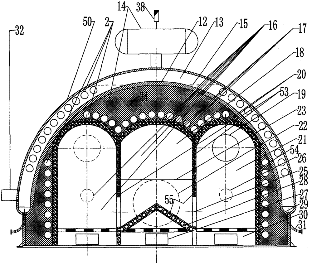
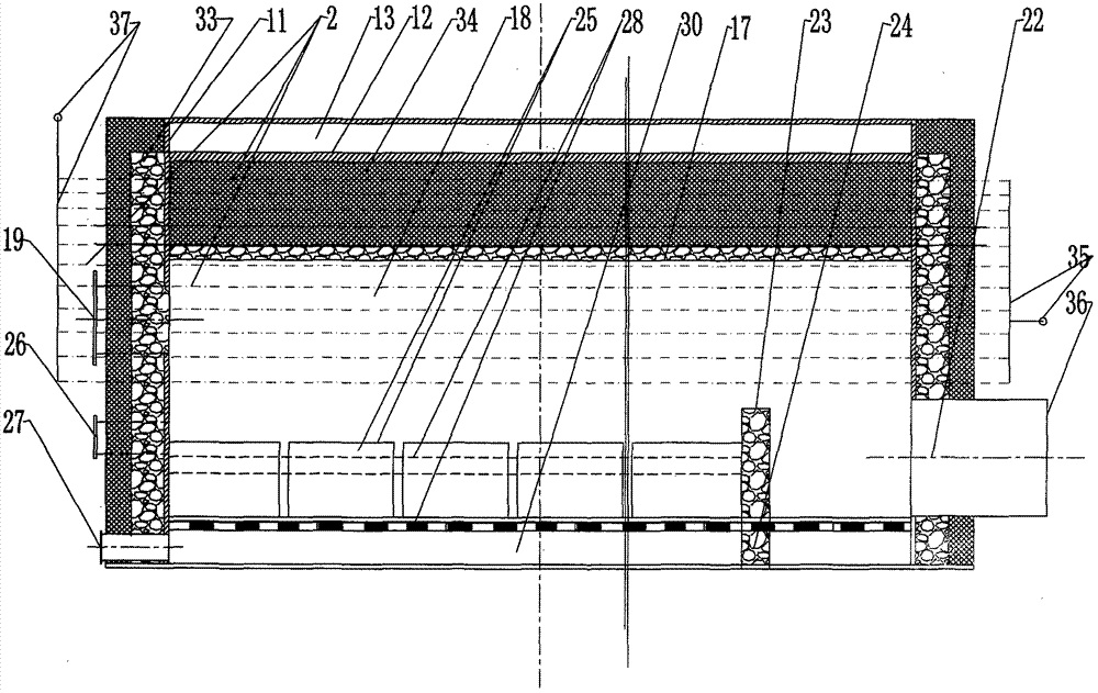
[0017] exist figure 1 In the semicircular furnace body 50 of the post-combustion hearth furnace 16, the inner tank half cylinder 12 and the semicircular pressure-bearing cylinder of the oil area 13 are built symmetrically with the two refractory middle walls 53 and the outer sides by the vacuum furnace hearth arch 17. The three arches of the gasification chamber arch 20 above the furnace wall 54 (the upper three arches and the outer sides of the furnace wall 54 are arranged along the arch wall in parallel closed inlet and outlet water flows and are filled by aluminum silicate felt filler 34 to the semicircular furnace body. 50 cooling in the thermal insulation layer), the vacuum furnace 18 in the corresponding space under the arch and the gasification chamber 21 symmetrical on both sides are the structural centers. The lower part of the cooling refractory middle wall 53 on both sides of the vacuum furnace 18 is left and right symmetrically opened through the burner 25 and onl...


PUM


Abstract

The invention relates to a CO2 energy power generation system technology with clean afterburning and multielement heat exchange of heat engine exhaust smoke. On the basis of original innovation of combustion science of the patent ZL201220566497.4 invented by the inventor, energy conservation and environment protection of appearing and hiding waste heat losses of heat engine exhaust smoke and CO2,SO2, NO and NO2 acid gas pollution need flue gas treatment, the technology is provided with an afterburning hearth furnace combustion CO2, three-array heat exchange unit and steam turbine cycle powergeneration system with heat engine exhaust smoke CO2 energy, (a steam turbine exhaust condensing system, a heat engine exhaust smoke, a low-temperature element array, a magnesium-catalyzing afterburning hearth furnace, a high temperature element array, waste heat low-temperature element array and a variable-frequency induced draught fan) and steam turbine combined cycle power generation by takinga afterburning hearth furnace as a center.

Description

technical field [0001] The present invention relates to a kind of CO that exhausts clean heat engine and recombustion and multi-element array heat exchange 2 Energy power generation system technology, especially in the ZL201210566497.4 patented magnesium catalyzed water-based combustion aid invented by myself Does not consume air, water-based combustion, ultra-efficient "Six-in-one super-efficient energy-saving and environmental protection" that can eliminate NOx generation, desulfurization, carbon dioxide reduction and carbon sequestration into slag On the basis of the original innovation of combustion science, all heat engines (internal-combustion engines and external-combustion engines for various locomotives and ships and various industrial and agricultural power, boilers for electric power, etc., but the most important supporting parts of the present invention are still locomotives and ships. Internal combustion engine, etc.) smoke exhaust has two kinds of waste heat lo...

Claims


Application Information

Patent Timeline
Patent Type & Authority Applications(China)
IPC IPC(8): F23C13/00F02G5/02F01K11/02
CPCY02T10/12
Inventor 管理
Owner 管理
Why Eureka
Try Eureka