Gradual transition layer for metal-based film sensor and preparation method

A thin film sensor and transition layer technology, applied in metal material coating process, coating, ion implantation plating and other directions, can solve problems affecting service life, cracks and cracks, etc., to avoid excessive oxidation, release internal stress, slow down The effect of rate and degree

Active Publication Date: 2018-01-12
UNIV OF ELECTRONICS SCI & TECH OF CHINA
View PDF4 Cites 10 Cited by
  • Summary
  • Abstract
  • Description
  • Claims
  • Application Information

AI Technical Summary

Problems solved by technology

This leads to the fact that the substrate is affected by thermal shock and thermal fatigue in practical applications, and cracks and cracks are extremely prone to occur, which affects its service life

Method used


Image

  • Gradual transition layer for metal-based film sensor and preparation method
  • Gradual transition layer for metal-based film sensor and preparation method
  • Gradual transition layer for metal-based film sensor and preparation method

Examples


preparation example Construction

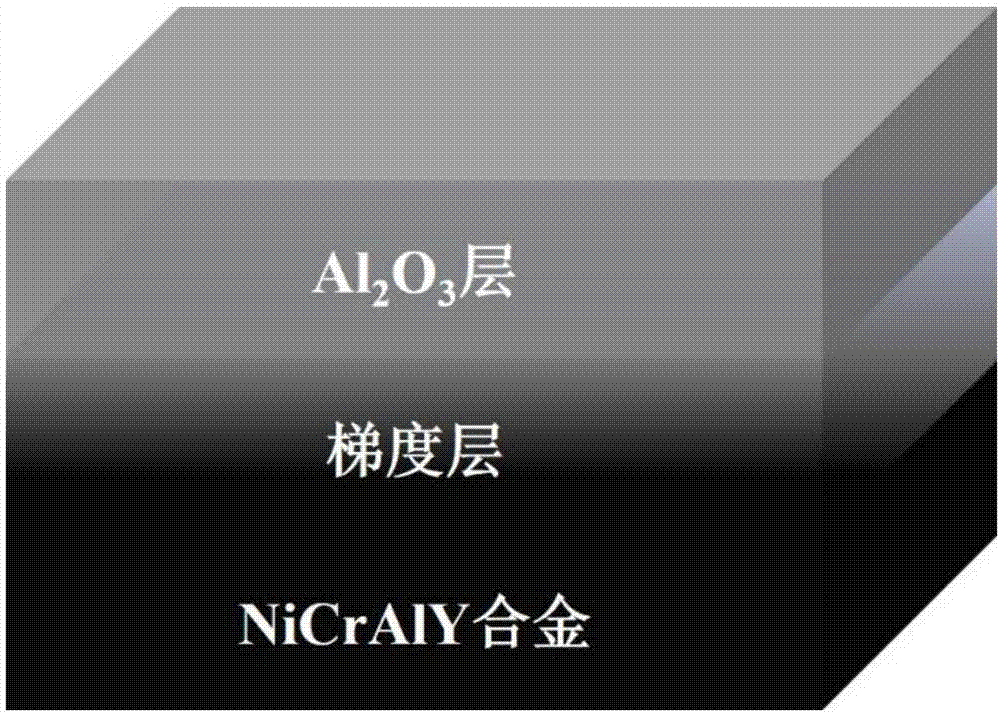
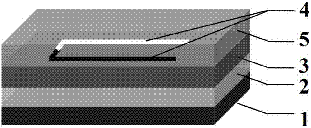
[0026] The invention provides a gradient transition layer for a metal-based film sensor, such as figure 2 As shown, it includes a three-layer structure, from bottom to top are NiCrAlY alloy layer, NiCrAlY alloy and Al 2 o 3 Gradient layer, Al 2 o 3 layer; thin-film sensors based on this graded transition layer include a five-layer structure, such as image 3 As shown, from bottom to top are nickel base alloy substrate 1, gradient transition layer 2, Al 2 o 3 Ceramic insulating layer 3, sensitive functional layer 4 and Al 2 o 3 protective layer5. The preparation method of this film sensor comprises the following steps:

[0027] Step 1. Surface treatment of the Ni-based alloy substrate: first, polish the surface of the alloy substrate, then use industrial degreaser, acetone, alcohol and deionized water to ultrasonically clean the alloy substrate successively, dry it with a nitrogen gun, and place it in an oven Dry in medium, and use plasma to clean the substrate before ...

Embodiment

[0037] In this embodiment, the nickel-based alloy plate is used as the alloy substrate to be tested, and the process of preparing the gradient transition layer of the present invention thereon includes the following steps:

[0038] Step 1. Preparation of NiCrAlY alloy layer: Put the polished and cleaned nickel-based alloy substrate on the back and the vacuum degree is 8.0×10 -4 In a vacuum environment of Pa, argon gas with a purity of 99.999% (volume percentage) is introduced as the sputtering medium, and NiCrAlY alloy is used as the target material, at a sputtering pressure of 0.4Pa, a sputtering power of 200W, and a substrate temperature of 500°C Under the condition of , the NiCrAlY alloy was deposited on the cleaned nickel-based alloy substrate by DC sputtering method, and the thickness of the deposited film was 10 μm;

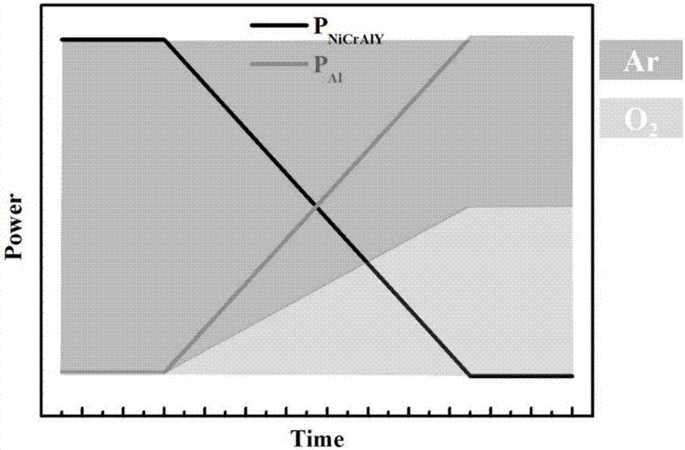
[0039] Step 2. NiCrAlY Alloy and Al 2 o 3 Preparation of the gradient layer: After the NiCrAlY alloy layer with a thickness of 10 μm is prepared in step ...


PUM

PropertyMeasurementUnit
thicknessaaaaaaaaaa
thicknessaaaaaaaaaa
thicknessaaaaaaaaaa

Abstract

The invention provides a gradual transition layer for a metal-based film sensor and a preparation method and belongs to the technical field of film sensors. The gradual transition layer comprises three layers of structures including a NiCrAlY alloy layer, a NiCrAlY alloy and Al2O3 gradient layer and an Al2O3 layer from bottom to top in sequence, wherein in the NiCrAlY alloy and Al2O3 gradient layer located in the middle, the concentration of NiCrAlY alloy decreases gradually in the growth direction of the film, and the concentration of Al2O3 increases gradually in the growth direction of the film. Compared with an existing transition layer, the gradual transition layer has the advantages that the heat treatment temperature is reduced by 200-400 DEG C; the heat treatment time is shortened by 50% or more; self-diffusion of nickel base alloy during high-temperature treatment and the rate and degree of mutual diffusion of the nickel base alloy and the NiCrAlY alloy are retarded; meanwhile,the heat treatment atmosphere is changed from a traditional oxygen-enriched environment to the atmospheric environment, and excessive oxidation of elements in the nickel base alloy is avoided to someextent.

Description

technical field [0001] The invention belongs to the technical field of thin-film sensors, in particular to thin-film sensors for testing surface state parameters of hot-end parts such as aero-engines. Accurate testing of parameters provides technical support for the design and optimization of aero-engines; it specifically relates to a gradient transition layer used between a metal base and a thin-film sensor and a preparation method. Background technique [0002] As the "heart" of aero-vehicles, aero-engines provide vital power for the development of aero-vehicles. Since the turbine blades and combustion chamber are in harsh environments such as high temperature, high pressure, and high air flow when the aero-engine is working, the temperature distribution and strain on its surface have a great impact on the performance and life of the aero-engine. Therefore, in the design and experimental research of modern aeroengines, it is very important to accurately measure performanc...

Claims


Application Information

Patent Timeline
Patent Type & Authority Applications(China)
IPC IPC(8): C23C14/34C23C14/16C23C14/08C23C14/58
Inventor 赵晓辉刘子良刘洋蒋洪川张万里
Owner UNIV OF ELECTRONICS SCI & TECH OF CHINA
Why Eureka
Try Eureka