

Chemical vapor deposition device and method for diamond coating on micro-tools
A technology of chemical vapor deposition and diamond coating, which is applied in the direction of metal material coating process, coating, gaseous chemical plating, etc., to solve the overall design and process problems, reduce the volume, and accelerate the growth rate.
- Summary
- Abstract
- Description
- Claims
- Application Information
AI Technical Summary
Problems solved by technology
Method used
Image

Examples
specific Embodiment approach 2
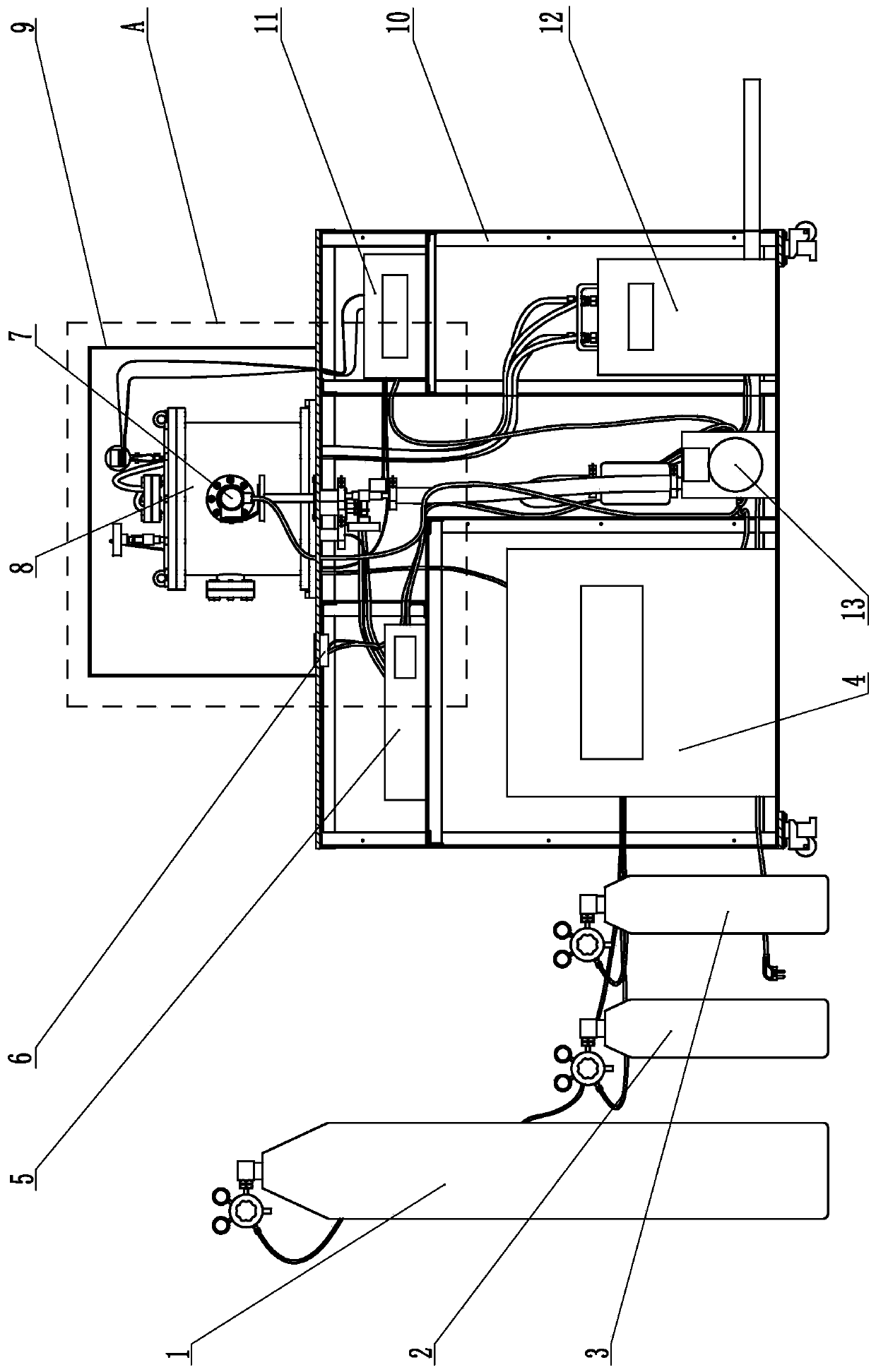
[0029] Specific implementation mode two: as figure 1 , Figure 4 As shown, this embodiment is a further description of the specific embodiment one. The chemical vapor deposition device for the micro-tool diamond coating also includes a dust cover 9; the dust cover 9 is buckled in the vacuum reaction chamber 8 (for convenience of observation and adjustment, the non-fixed connection between the dust cover 9 and the workbench base 10).
specific Embodiment approach 3
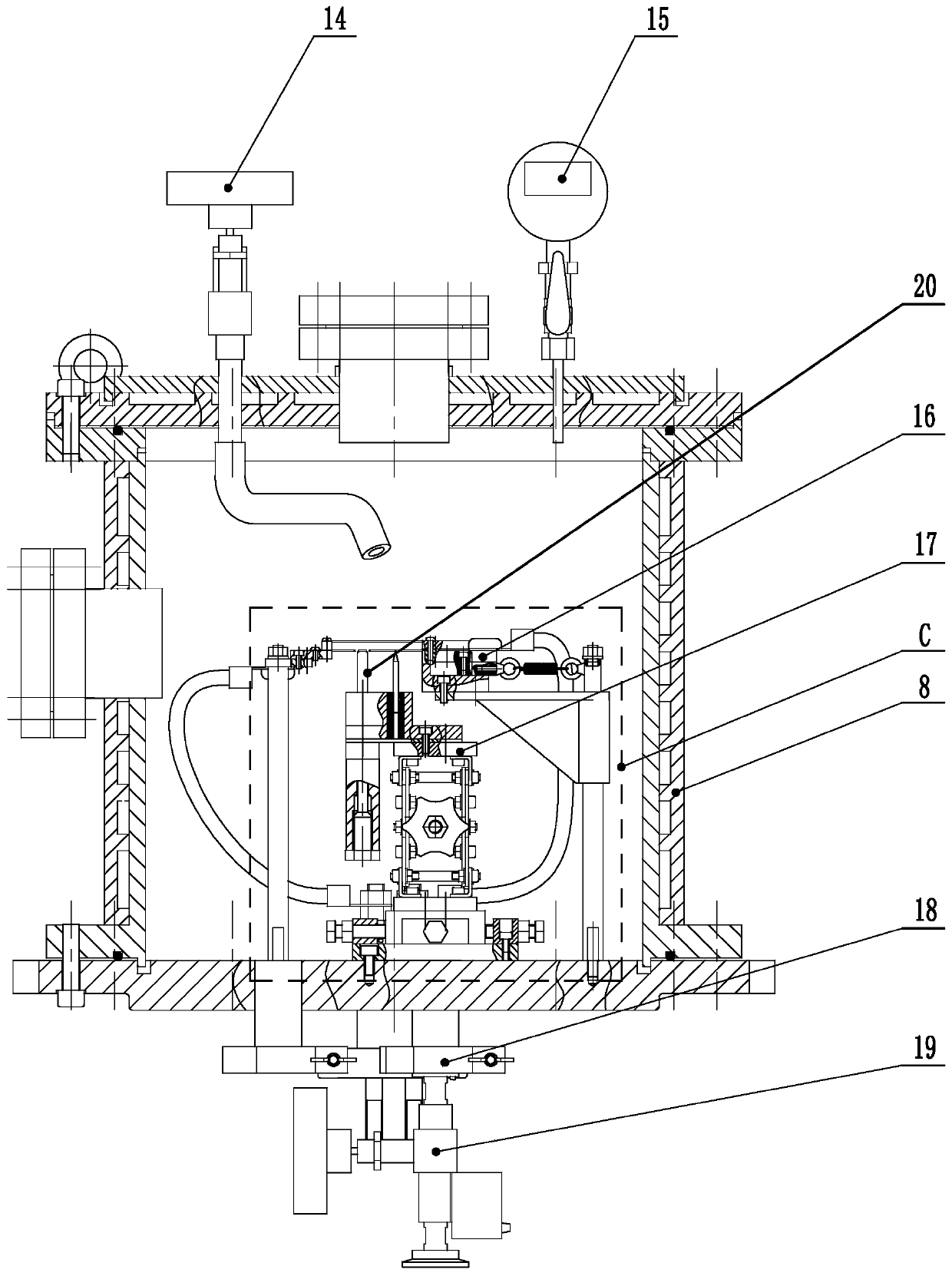
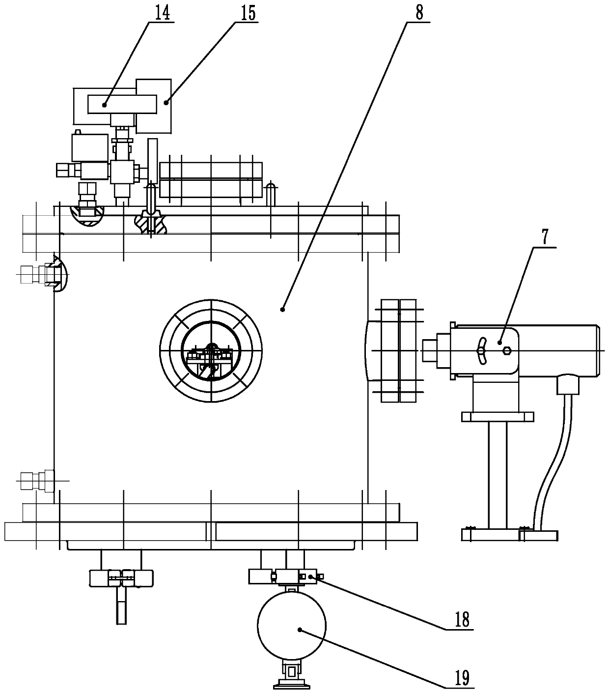
[0030] Specific implementation mode three: as Figure 1-Figure 3 As shown, this embodiment is a further description of specific embodiment 1. The vacuum needle valve 19 is connected with the vacuum reaction chamber 8 through a clamp 18, a KF external thread adapter and a KF joint (that is, the vacuum needle valve 19 The thread is connected with the KF external thread adapter, the KF joint is connected with the vacuum reaction chamber 8, and the KF external thread adapter and the KF joint are connected by a clamp to ensure airtightness).
[0031] Specific implementation mode four: as figure 1 As shown, this embodiment is a further description of specific embodiment one. The hydrogen cylinder 1, the argon cylinder 2, and the methane cylinder 3 are all equipped with pressure reducing valves (which can ensure that the output of the gas pressure is within a certain range. , and protect the pipeline connected to it).
specific Embodiment approach 5
[0032] Embodiment 5: This embodiment is a further description of Embodiment 1. The three heating wires are arranged in parallel spatially and horizontally (to form a uniform temperature field near the micro-cutter substrate).
[0033] Specific implementation mode six: as figure 2 , image 3 , Figure 6 As shown, this embodiment is a further description of Embodiment 1. The electrode assembly 16 enters the vacuum reaction chamber 8 through the KF flange and the KF joint, and the KF flange and the KF joint pass through the clamp 18 and O-ring connection (that is, the vacuum reaction chamber 8 furnace cover is connected with the KF joint, the O-ring is placed between the KF flange and the KF joint, and the KF flange and the KF joint are connected through the clamp 18, and pressed O type sealing ring to ensure air tightness).
PUM
 Abstract
Description
Claims
Application Information