

Transformer-coupled voltage-controlled oscillator with long service life
A voltage-controlled oscillator and transformer coupling technology, applied in the direction of power oscillators, electrical components, etc., to achieve the effect of reducing the size of the inductor, reducing the phase noise, and reducing the chip area
- Summary
- Abstract
- Description
- Claims
- Application Information
AI Technical Summary
Problems solved by technology
Method used
Image

Examples
Embodiment 1
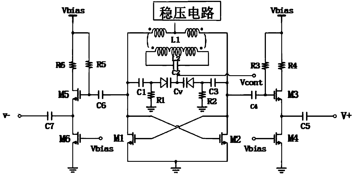
[0029] Such as Figure 1-5 As shown, the present invention includes a transformer-coupled voltage-controlled oscillator with long service life, including an interconnected core oscillating circuit and an output buffer stage circuit, and the core oscillating circuit includes a voltage stabilizing circuit, an inductance-capacitance resonant circuit and a negative resistance generation circuit, The differential inductance L1 of the primary coil and the inductance L2 of the secondary coil on the inductance-capacitance resonant circuit are magnetically coupled through the transformer structure, and the negative resistance generation circuit is composed of NMOS tube M1 and NMOS tube M2 with a cross-coupling structure, and the NMOS tube M1 in the negative resistance generation circuit The drain of the NMOS tube M2 is connected to the parallel junction of the main coil inductance L1 and the fixed capacitor C1 in the inductor-capacitor resonance circuit, and the drain of the NMOS tube M...
Embodiment 2
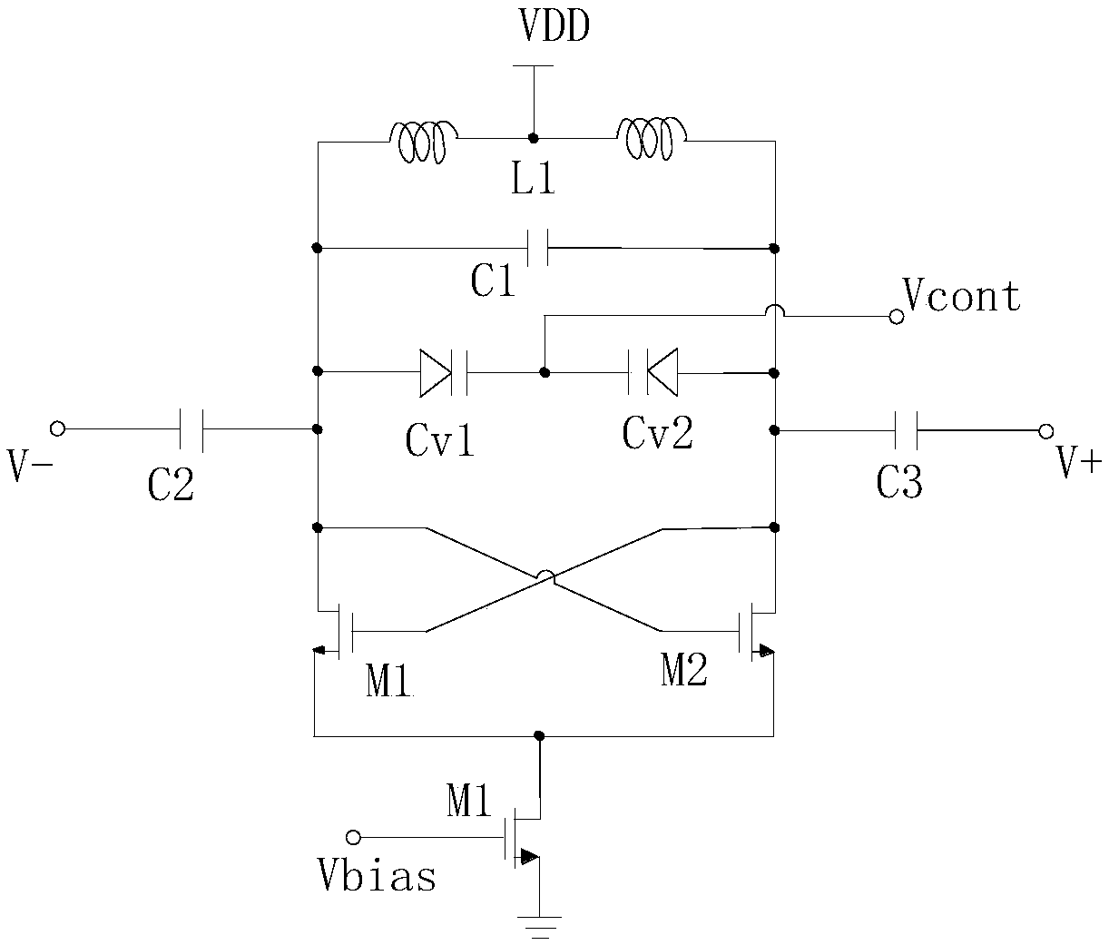
[0036] This embodiment is preferably as follows on the basis of Embodiment 1: the inductance-capacitance resonant circuit includes a primary coil differential inductance L1, a secondary coil inductance L2, a fixed capacitor C1, a fixed capacitor C2, and a differential varactor diode Cv, and the primary coil differential inductance L1 and the secondary coil inductance L2 are magnetically coupled through the transformer structure; the common tap end of the main coil differential inductance L1 is connected to the positive voltage of the VDD power supply, and the other two ends of the main coil differential inductance L1 are respectively connected to the positive pole of the fixed capacitor C1 and one end of the fixed capacitor C2 The other end of the fixed capacitor C1 is connected to one pole of the differential varactor diode Cv, the other end of the fixed capacitor C2 is connected to the other pole of the differential varactor diode Cv, and the common terminal of the differentia...
Embodiment 3
[0051] This embodiment is preferably as follows on the basis of the above embodiments: the inductor-capacitor resonant circuit also includes a resistor R1 and a resistor R2, one end of the resistor R1 is connected to one pole of the differential varactor diode Cv, the other end of the resistor R1 is grounded, and one end of the resistor R2 is connected to the differential variable capacitance The other pole of the capacitor diode Cv, and the other end of the resistor R2 is grounded. Applying large resistors R1 and R2 can effectively prevent the oscillating signal generated in the main circuit from reaching the ground.
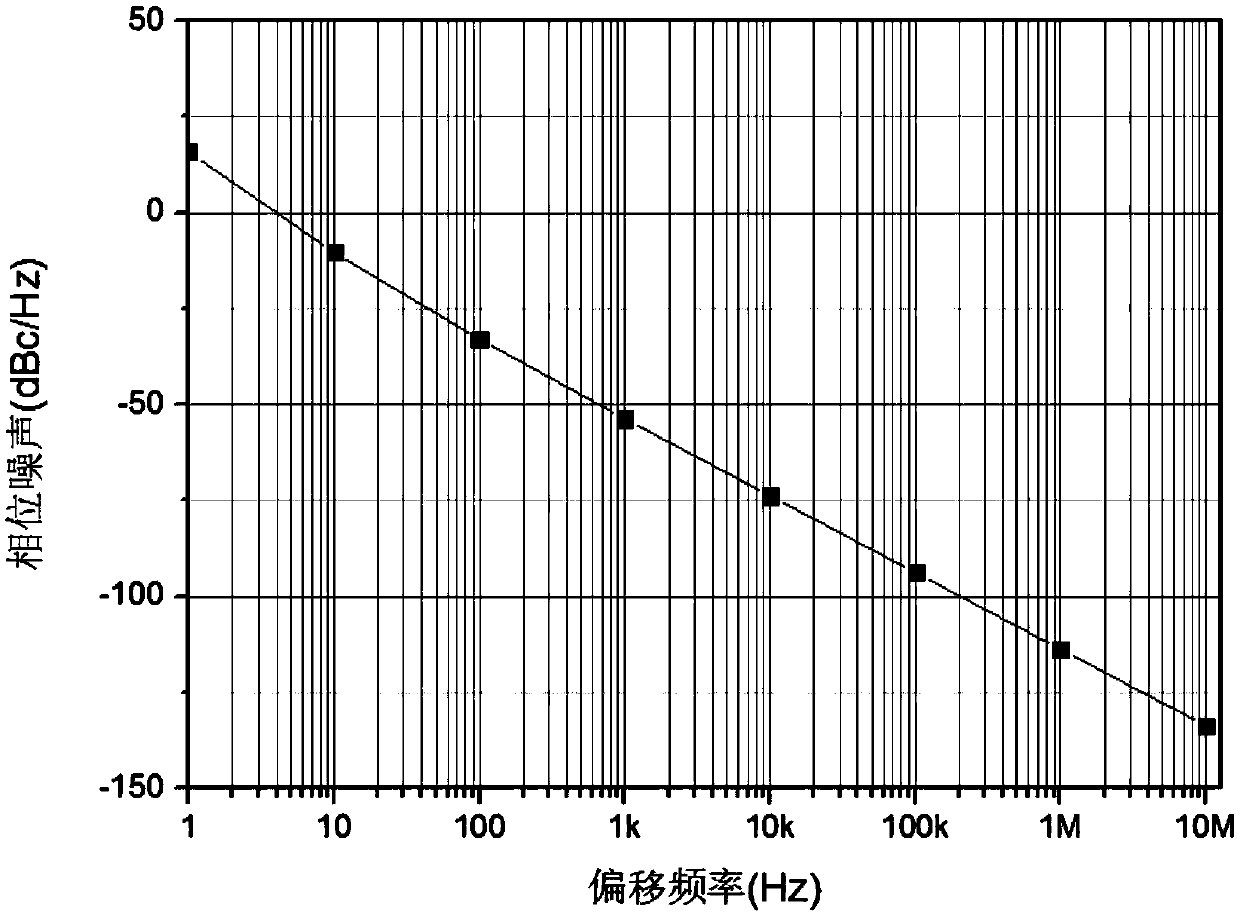
[0052] The circuit is integrated using IBM's standard 0.13μm BiCMOS process. By coupling the differential inductance in the main circuit and the single-turn inductance in the secondary circuit through the transformer structure, while reducing the area of the inductance, the quality factor of the LC resonant circuit is increased to improve the phase noise perf...
PUM
 Abstract
Description
Claims
Application Information