Chemiluminescent detection microfluidic chip and chemiluminescent detection microfluidic chip system and application thereof

A chemiluminescence detection, microfluidic chip technology, applied in the application of chemiluminescence detection, chemiluminescence detection microfluidic chip system, chemiluminescence detection microfluidic chip field, can solve single sample detection accuracy decline, capillary Problems such as uneven force and large changes in chip structure have achieved the effect of strong detection repeatability, wide linear range, and avoiding interference and pollution problems

Pending Publication Date: 2018-04-20
丁锐
View PDF15 Cites 35 Cited by
  • Summary
  • Abstract
  • Description
  • Claims
  • Application Information

AI Technical Summary

Problems solved by technology

[0007] However, there are very few patents on the use of microfluidic chip technology for chemiluminescence in vitro diagnosis, and there are fewer domestic and foreign companies that combine these two technologies to develop mature chip products
After patent research, it was found that there have been a small number of patents using microfluidic technology for chemiluminescence detection at home and abroad in recent years. For example, Chinese patent 201510696773 discloses a magnetic particle chemiluminescence microfluidic chip, but there is no reagent or sample in the chip. The quantitative unit cannot determine the sample volume participating in the reaction, which will easily lead to a decrease in detection accuracy, and the microchannel structure in the chip is completely closed. Once bubbles are introduced, it will make it difficult for the entire chip to complete subsequent detection; another example is Chinese patent 201611033217. A microfluidic paper chip and its chemiluminescent immunoassay method, but the chip uses capillary action to complete the sample injection, the internal paper structure of different chips varies greatly, and the capillary force is uneven and difficult to control. The repeatability between samples is relatively poor, and the detection accuracy of a single sample will be greatly reduced

Method used


Image

  • Chemiluminescent detection microfluidic chip and chemiluminescent detection microfluidic chip system and application thereof
  • Chemiluminescent detection microfluidic chip and chemiluminescent detection microfluidic chip system and application thereof
  • Chemiluminescent detection microfluidic chip and chemiluminescent detection microfluidic chip system and application thereof

Examples


preparation example Construction

[0083] The preparation method of the chemiluminescent detection microfluidic chip provided by the present invention preferably includes the following steps:

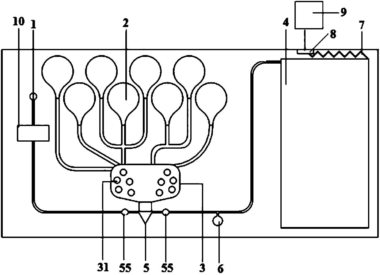
[0084] Step 1) preload the reagents required for the chemiluminescence reaction into the reagent pouch 21, and seal the sealing port 212 of the reagent pouch 21 by means of thermoplastic sealing; and place it on the chip through the positioning hole 211 At the specific liquid storage structure of the middle layer structure of the system, the reagent pouches 21 for each liquid storage are further fixed on the middle layer structure of the chip system by means of thermal plastic sealing.

[0085] Step 2) Bonding the lower structure to the lower part of the upper middle structure, the bonding methods include but not limited to ultrasonic melting, adhesive, ultraviolet curing, thermoplastic sealing and other methods.

[0086] Step 3) Attaching the upper structure to the upper middle structure, the attachment methods include ...

Embodiment 1

[0097] This example is used to illustrate the use of magnetic particle chemiluminescence to detect C-reactive protein (CRP) in whole blood

[0098] The enzyme-labeled antibody used in this example is horseradish peroxidase-labeled CRP (HRP-CRP), the size of the magnetic particles in the magnetic particle-labeled CRP is about 5 μm, and the cleaning solution contains 0.2 volume % BSA, 0.5 volume % tween -20 phosphate buffer solution (pH 7.5), the first luminescent base solution is an acidic solution containing luminol, and the second luminescent base solution is an alkaline solution containing benzene derivatives.

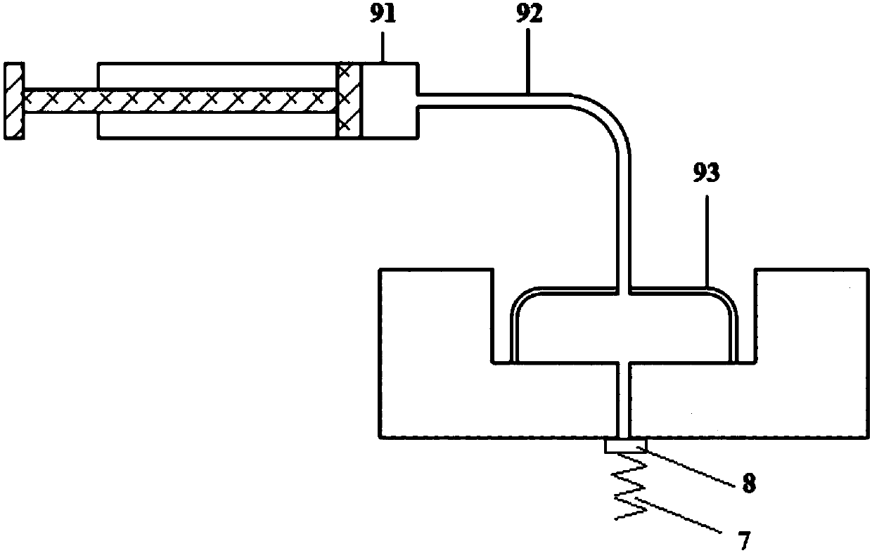
[0099] (1) Assembly of chip system

[0100] The above-mentioned reaction reagents are prepacked in the reagent pouch 21, and the sealing port 212 of the reagent pouch 21 is sealed by means of thermoplastic sealing (heating time 30s); and placed in the middle layer structure of the chip system through the positioning hole 211 At the specific liquid storage structure,...

Embodiment 2

[0108] This example is used to illustrate the detection of C-reactive protein (CRP) in whole blood by the coated antibody chemiluminescence method

[0109] The enzyme-labeled antibody used in this embodiment is horseradish peroxidase-labeled CRP (HRP-CRP), and the cleaning solution is a phosphate buffer (pH 7.5) containing 0.2 volume % BSA and 0.5 volume % tween-20. The first luminescent base liquid is an acidic solution containing luminol, and the second luminescent base liquid is an alkaline solution containing benzene derivatives. The coated antibody is a C-reactive protein solution, which is injected into the reaction unit 3 by spotting the sample, and baked at 40°C for 3 hours after spotting, so that the CRP protein spotted at the reaction unit 3 is adsorbed and fixed. in the reaction chamber.

[0110] The detection process is the same as in Example 1.

[0111] The results showed that the minimum detection limit of CRP concentration detection by the coating antibody met...


PUM

PropertyMeasurementUnit
thicknessaaaaaaaaaa
thicknessaaaaaaaaaa
widthaaaaaaaaaa

Abstract

The invention relates to the technical field of microfluidic chip chemiluminescent immunoassay, in particular to a chemiluminescent detection microfluidic chip and a chemiluminescent detection microfluidic chip system and application thereof. The chemiluminescent detection microfluidic chip comprises a sample feeding unit (1), a liquid storage unit (2), a reaction unit (3) and a waste liquid unit(4), and further comprises a quantifying unit (5) for quantifying a sample to be detected, wherein the quantifying unit (5) comprises a liquid inlet (51) connected with the sample feeding unit, a liquid outlet (52) connected with the waste liquid unit, a quantifying structure (53) for quantifying, and a temporary storage structure (54) for temporarily storing excess liquid, which is connected withthe reaction unit. The chemiluminescent detection microfluidic chip system consists of three layers, namely an upper layer, a middle layer and a lower layer; the middle layer is the chip; the upper layer and the lower layer are used for closing the middle layer; the upper layer is provided with a sample feeding hole connected with the sample feeding unit and a yielding hole corresponding to the liquid storage unit. The chemiluminescent detection microfluidic chip is simple in detection process, can quantify the reaction sample and has high sensitivity and strong repeatability.

Description

technical field [0001] The invention relates to the technical field of chemiluminescence immunodetection of microfluidic chips, in particular to a chemiluminescent detection microfluidic chip and a chemiluminescent detection microfluidic chip system, and their application in chemiluminescent detection. Background technique [0002] Microfluidic chip technology, also known as microfluidic chip lab or chip lab, refers to a chemical or biological laboratory built on a chip of a few square centimeters. The basic operation units such as sample preparation, reaction, separation, detection, cell culture, sorting, and lysis are integrated on a small chip, and a network of microchannels is formed to run through the entire system with controllable fluids to realize biological, chemical , various functions in fields such as medical diagnosis. [0003] The basic characteristics and biggest advantages of microfluidic chip technology are: a variety of unit structures can be flexibly comb...

Claims


Application Information

Patent Timeline
Patent Type & Authority Applications(China)
IPC IPC(8): B01L3/00G01N21/76
CPCG01N21/76B01L3/5027B01L2200/10
Inventor 丁锐
Owner 丁锐
Why Eureka
Try Eureka