a cracking furnace

A cracking furnace and furnace wall technology, which is applied in cracking, non-catalytic thermal cracking, petroleum industry, etc., can solve the problems of insufficient heat transfer area of ​​cracking furnace furnace, reduce the operation cycle of cracking furnace, and the local temperature of furnace tube is high, so as to occupy an area The effect of small area, reducing the difficulty of layout and prolonging the operation cycle

Active Publication Date: 2020-02-18
CHINA PETROLEUM & CHEM CORP +1
View PDF5 Cites 0 Cited by
  • Summary
  • Abstract
  • Description
  • Claims
  • Application Information

AI Technical Summary

Problems solved by technology

[0010] There are two problems in the current heat transfer process of the cracking furnace hearth. One is that the heat transfer area of ​​the cracking furnace furnace is insufficient, and the heat transfer process of the cracking furnace furnace is mainly radiation heat transfer; There is no difference, that is, the furnace wall of the cracking furnace has the same heat transfer area for the inlet tube row and the outlet tube row, and it is the same for the area with large heat flux and the area with small heat flux, which will lead to Partial heating is uneven, resulting in excessive local temperature of the furnace tube, reducing the operating cycle of the cracking furnace

Method used


Image

  • a cracking furnace
  • a cracking furnace
  • a cracking furnace

Examples


Embodiment 1

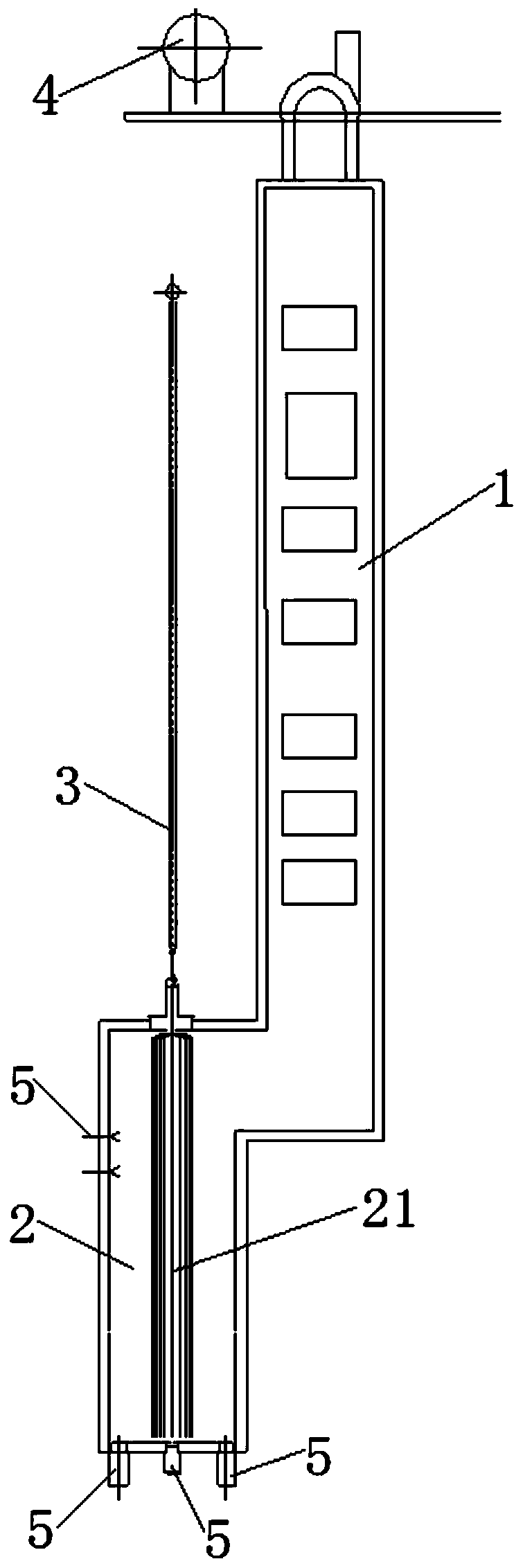
[0066] use figure 1 The cracking furnace shown carries out the cracking reaction. The specific process includes:

[0067] Naphtha at 60°C is gasified and preheated in the convection section 1 and then enters the radiant furnace tube 22 of the radiant section 2 for cracking reaction. The combustion system of the radiant section 2 adopts a combination of bottom burners and side wall burners. The heat supply ratio of the burner is 80%; the burner 5 adopts oxygen-enriched combustion, and the oxygen concentration is 30% (volume fraction). The temperature at which naphtha is preheated in the convection section 1, that is, the cross-over temperature (XOT) of the cracking furnace is 590°C, the outlet temperature (COT) of the radiant section 2 of the cracking furnace is 830°C, and the radiant furnace tube 22 of the radiant section 2 adopts a single pass Furnace tube, the inlet diameter of the furnace tube is 41mm, the outlet diameter of the furnace tube is 53mm, the length of the fur...


PUM


Abstract

The invention discloses a cracking furnace. The cracking furnace comprises a convection section, a radiation section communicated with the convection section, a quenching boiler and a steam drum, wherein the convection section is internally provided with a convection tube bundle communicated with a feed inlet of the cracking furnace; the steam drum is arranged on the top of the convection section;the top of the convection section is provided with a fan communicated with the cracking furnace; the radiation section is internally provided with a plurality of groups of radiation tube bundles; theradiation tube bundles comprise a plurality of radiation furnace tubes; the plurality of radiation furnace tubes are arranged along the peripheries of the radiation tube bundles at intervals; the radiation furnace tubes are communicated with the convection tube bundle; the bottom and sidewall of a hearth in the radiation section are separately provided with a plurality of combustors; and the outlet ends of the radiation furnace tubes are communicated with the quenching boiler. According to the cracking furnace provided by the invention, through improvement of the arrangement mode of the radiation furnace tubes, difficulties in arrangement of the radiation furnace tubes can be reduced, and reaction conditions in each group of radiation furnace tubes in the cracking furnace are maximally maintained same; and the cracking furnace has the advantage of a small occupied land area under the condition of same unit production capacity.

Description

technical field [0001] The invention relates to the technical field of petroleum hydrocarbon steam cracking in a tubular furnace, in particular to a cracking furnace adopting an oxygen-enriched combustion system. Background technique [0002] Low-carbon olefins such as ethylene, propylene and butadiene are important basic raw materials for the petrochemical industry. At present, the method for producing low-carbon olefins is mainly based on the tube furnace petroleum hydrocarbon steam cracking process. According to statistics, about 99% of ethylene, more than 50% of propylene and more than 90% of butadiene in the world are produced through this process. [0003] The core equipment of the tubular furnace petroleum hydrocarbon steam cracking process is the tubular cracking furnace (hereinafter referred to as the "cracking furnace"). When the cracking raw materials such as ethane, propane, naphtha and hydrogenated tail oil are heated to high temperature in the cracking furnace...

Claims


Application Information

Patent Timeline
Patent Type & Authority Patents(China)
IPC IPC(8): C10G9/20
CPCC10G9/20
Inventor 王国清张利军周丛杜志国刘俊杰张永刚张兆斌
Owner CHINA PETROLEUM & CHEM CORP
Why Eureka
Try Eureka