Particle vibration velocity measurement sensitive structure and preparation method thereof

A sensitive structure and particle velocity technology, applied in the direction of measuring devices, microstructure technology, microstructure devices, etc., can solve the problems that limit the wide application of particle velocity measurement sensors, the lower limit of the effective working frequency of sensors, and the deterioration of sensor response characteristics. Achieve the effect of suppressing heat conduction effect, reducing effective cross-sectional area, and ensuring response sensitivity

Active Publication Date: 2018-05-25
THE THIRD RES INST OF CHINA ELECTRONICS TECH GRP CORP
View PDF9 Cites 10 Cited by
  • Summary
  • Abstract
  • Description
  • Claims
  • Application Information

AI Technical Summary

Problems solved by technology

[0004] The disadvantage of the existing particle velocity measurement sensitive structure is that due to the material properties of the above-mentioned particle velocity measurement sensor sensitive structure and its topological structure have a finite length boundary heat conduction effect, the loss rate of heat from the boundary is higher than that caused by low-frequency sound waves. The heat exchange rate caused by the sensor makes the response characteristics of the sensor worse in the low frequency band
In the low-frequency band below 100Hz, the sens

Method used


Image

  • Particle vibration velocity measurement sensitive structure and preparation method thereof
  • Particle vibration velocity measurement sensitive structure and preparation method thereof
  • Particle vibration velocity measurement sensitive structure and preparation method thereof

Examples


Embodiment 1

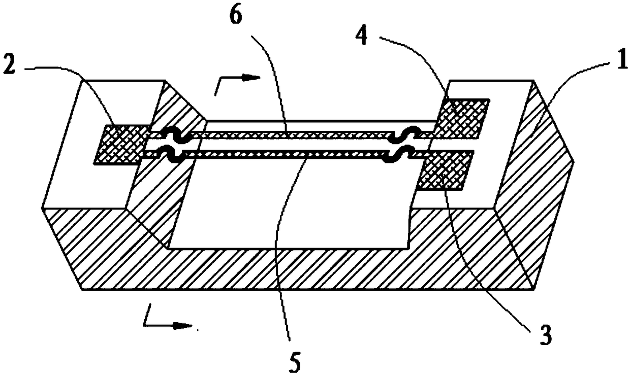
[0040] Such as figure 1 As shown, a bridge hole is formed on the silicon substrate 1, a first electrode 2 is provided on one side of the bridge hole, and a second electrode 3 and a third electrode 4 are provided on the other side of the bridge hole, which is the prior art. A first thin wire 5 and a second thin wire 6 are arranged above the bridge hole, and the first thin wire 5 and the second thin wire 6 are arranged in parallel and keep a small distance. One end of the two thin wires is connected to the first electrode 2, and the two The other end of the thin wire is connected 4 with the second electrode 3 and the third electrode respectively. The structures of the first thin wire 5 and the second thin wire 6 are both, and the two ends of the thin wire are curved. When implemented, the two ends of the thin wire are in the shape of an S or in the shape of "几". In this embodiment, , both ends of the thin wire are S-shaped. The middle part of the thin wire is straight and rect...

Embodiment 2

[0042] In the second embodiment, a thin wire is arranged between the first thin wire and the second thin wire, and the said one thin wire is arranged in parallel with the first thin wire and the second thin wire, and its structure is the same as that of the first thin wire and the second thin wire. The two thin threads are the same. The width of the thin wire in the middle part of the thin wire is 8 μm, and the thickness is 0.2 μm. The width of the thin wire at both ends of the thin wire was 0.5 μm, and the thickness was 0.08 μm. All the other structures are the same as in Embodiment 1.

Embodiment 3

[0044] The preparation method of the particle vibration velocity measurement sensitive structure of the present invention comprises the following steps:

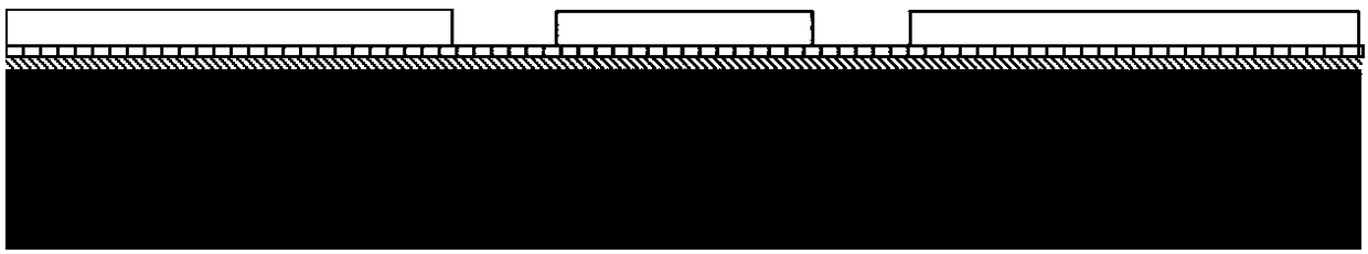
[0045] Step 1: If figure 2 As shown, a thermal insulation layer and a support layer are sequentially deposited on a silicon substrate, wherein the thermal insulation layer is located below the support layer;

[0046] Step 2: If image 3 As shown, the first gluing, photolithography and development are carried out to define the first electrode, the second electrode, the third electrode and the first sensitive layer of the particle vibration measurement sensitive structure. The first sensitive layer is the two sides of the thin wire. end part;

[0047] Step 3: If Figure 4 As shown, the adhesion layer and the first sensitive layer are sequentially evaporated and deposited, wherein the adhesion layer is located below the first sensitive layer;

[0048] Step 4: If Figure 5 As shown, the photoresist is stripped to form a corr...


PUM

PropertyMeasurementUnit
Widthaaaaaaaaaa
Thicknessaaaaaaaaaa
Widthaaaaaaaaaa

Abstract

The invention relates to a particle vibration velocity measurement sensitive structure and a preparation method thereof. A bridge hole is formed in a silicon substrate, a first electrode is arranged on one side of the bridge hole, a second electrode and a third electrode are arranged on the other side of the bridge hole, a first thin wire and a second thin wire are arranged above the bridge hole,the first thin wire and the second thin wire are arranged in parallel and keep a fine pitch, one end of each of the two thin wires is respectively connected with the first electrode, the other end ofeach of the two thin wires is respectively connected with the second electrode and the third electrode, and both the first thin wire and the second thin wire have a structure that both end parts of the thin wire are curved and the middle part of the thin wire is a straight rectangular shape; and the width and thickness of the middle part of the thin wire are greater than the width and thickness ofboth end parts of the thin wire. According to the scheme of the invention, both end parts of each thin wire adopt a narrow, thin and curved unique structure, the effective cross-sectional area of heat conduction through the thin wires can be reduced, the length of a heat transfer path can also be increased, and thus the finite length boundary heat conduction effect of the sensitive structure canbe effectively suppressed, and the response characteristics in low frequency bands can be improved.

Description

technical field [0001] The invention relates to a particle vibration velocity measurement sensitive structure and a preparation method. Background technique [0002] In a large number of acoustic measurement applications, because the sound intensity measurement and its spectrum analysis have unique advantages in the study of the characteristics of the noise source, it has become a powerful tool for acoustic research. Usually, the acquisition of sound intensity information requires the measurement of sound pressure and particle velocity in the sound field. [0003] The sensitive structure of the existing particle vibration velocity sensor is to prepare a sensitive structure composed of several metal platinum resistance wires (thin wires) that are very close to each other on the silicon substrate by using the MEMS process technology, which can directly measure the spatial sound field The vibration velocity of media molecules caused by propagation—the vibration velocity of sou...

Claims


Application Information

Patent Timeline
IPC IPC(8): B81B3/00B81C1/00G01H11/06
Inventor 刘云飞周瑜冯杰
Owner THE THIRD RES INST OF CHINA ELECTRONICS TECH GRP CORP
Why Eureka
Try Eureka