Treating method and treating apparatus for waste liquid produced in flue gas desulfurization

A desulfurization waste liquid and treatment device technology, which is applied in gaseous effluent wastewater treatment, gas treatment, filtration treatment, etc., can solve the problems of increasing the desulfurization waste liquid treatment scale, unable to effectively solve the problems of white smoke and high investment, and achieves a floor space of Small, reduced equipment investment and operating energy consumption, good treatment effect

Active Publication Date: 2018-06-05
CHINA PETROLEUM & CHEM CORP +1
View PDF11 Cites 5 Cited by
  • Summary
  • Abstract
  • Description
  • Claims
  • Application Information

AI Technical Summary

Problems solved by technology

[0005] CN102335553A The sodium-based flue gas desulfurization waste liquid is passed into the bipolar membrane electrodialysis device, and the desulfurization absorbent is regenerated by relying on the selective permeation of the membrane and the electrolysis device, and sulfuric acid is produced as a by-product, realizing "zero discharge" of the desulfurization waste liquid , but the technology consumes more power
CN104801162A uses ammonia water as reducing agent and absorbent to carry out denitrification and desulfurization treatment on flue gas respectively, and removes mist droplets with wet electric demister to purify flue gas, which

Method used


Image

  • Treating method and treating apparatus for waste liquid produced in flue gas desulfurization
  • Treating method and treating apparatus for waste liquid produced in flue gas desulfurization
  • Treating method and treating apparatus for waste liquid produced in flue gas desulfurization

Examples


Embodiment 1

[0047] The composition of sulfur-containing flue gas after denitration treatment of a boiler flue gas is shown in Table 1.

[0048] Table 1 The composition of sulfur-containing flue gas after denitrification of a boiler flue gas

[0049]

[0050] Calculate the dew point temperature of flue gas acid (sulfuric acid) before desulfurization treatment according to the following formula:

[0051]

[0052] in,[ H 2 O ]——Water vapor content in flue gas, vol%.

[0053] [ SO 3 ]--cigarette

[0054] Different water vapor content and different SO 3 The dew point temperature of sulfuric acid at the concentration is shown in Table 2.

[0055] Table 2 Different water vapor content and SO 3 Flue gas dew point temperature at content

[0056]

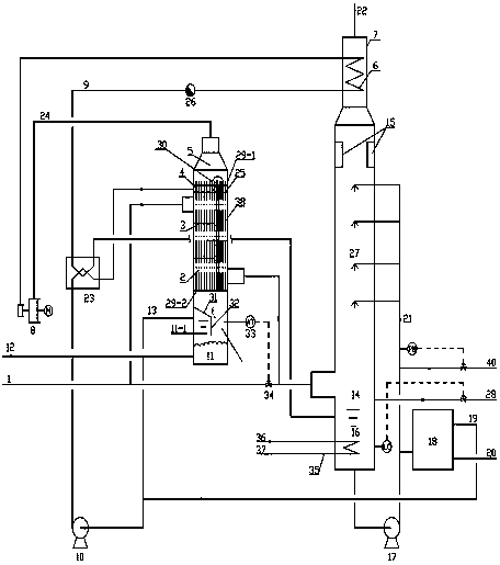
[0057] Using the present invention figure 1 The treatment device: the flue gas / desulfurization waste liquid heat exchanger adopts a vertical shell-and-tube heat exchanger, the flue gas goes on the shell side, the desulfurization wast...

Embodiment 2

[0061] SO in flue gas to be treated 2 Concentration 2000mg / Nm 3 , SO 3 Concentration 160mg / Nm 3 , and other parameters are the same as in Example 1.

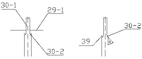
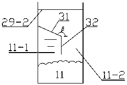
[0062] Using the present invention figure 1 The processing device: the specification of the heat exchange tube is DN25, and the flow rate of the desulfurization waste liquid in the heat exchange tube is 3m / s. The dust removal and desulfurization area adopts the form of absorbent spraying. The vertical distance between the upper tube sheet and the top of the heat exchange tube is 20mm; the bottom guide groove is inserted into the heat exchange tube, and the insertion length is 20mm; the axial angle α of the bottom end of the guide groove is 40°. The angle β between the guide plate and the horizontal direction is 120°, and the sealing plate is inserted below the liquid surface of the crystallization tank. The solid-liquid separator is precision filtration.

[0063] Operating conditions: (1) The absorbent adopts 30% NaOH sol...

Embodiment 3

[0066] To-be-treated flue gas SO 2 Concentration 3000mg / Nm 3 , SO 3 Concentration 260mg / Nm 3 , and other parameters are the same as in Example 1.

[0067] Using the present invention figure 1 The treatment device: the specification of the heat exchange tube is DN40, and the flow rate of the desulfurization waste liquid in the heat exchange tube is 3m / s. The dust removal and desulfurization area adopts the form of absorbent spraying. The vertical distance between the upper tube sheet and the top of the heat exchange tube is 40mm; the bottom guide groove is inserted into the heat exchange tube, and the insertion length is 40mm; the axial angle α of the bottom end of the guide groove is 50°. The angle β between the guide plate and the horizontal plane is 140°, and the sealing plate is inserted below the liquid surface of the crystallizing tank. The solid-liquid separator is "flocculation + drum filtration".

[0068] Operating conditions: (1) The absorbent adopts 40% NaOH s...


PUM


Abstract

The invention relates to a treating apparatus for waste liquid produced in sodium-process flue gas desulfurization. The treating apparatus mainly comprises a flue gas/desulfurization waste liquid heatexchanger, a dust-removal and desulfurization tower, a solid-liquid separator, a plate heat exchanger and a steam compressor, wherein the flue gas/desulfurization waste liquid heat exchanger is divided into an upper heat exchange zone and a lower crystallization zone; the upper heat exchange zone comprises a steam chamber, an upper tube plate, a partition plate, a heat exchange tube and a lower tube plate from top to bottom; a desulfurization waste liquid feeding box is arranged between the upper tube plate and the partition plate; a liquid film former is arranged at the heat exchanger tube end of the desulfurization waste liquid feeding box; the lower crystallization zone is provided with an inclined drainage plate, a sealing plate and a crystallization tank; and the sealing plate is inserted into a position located below the liquid level of the crystallization tank. Through adoption of the specific treating apparatus and a specific treating method, the dual purposes of allowing purified flue gas to meet emission requirements and realizing zero discharge of waste liquid produced in flue gas desulfurization are achieved on the basis of full use of the waste heat of flue gas; and in particular, the supplementation amount of fresh water for a flue gas desulfurization system is reduced, and overall treatment cost of flue gas desulfurization and desulfurization waste liquid is lowered.

Description

technical field [0001] The invention belongs to the field of environmental protection wastewater treatment, and particularly relates to a treatment method and a treatment device for a sodium-method flue gas desulfurization waste liquid. Background technique [0002] Since 2003, my country's SO 2 Total emissions have remained high. In 2014, my country's SO 2 The total amount of emissions was 19.744 million tons, the first time since 2003 that it was below 20 million tons. Commonly used flue gas desulfurization methods mainly include dry method and wet method. Compared with dry desulfurization, wet desulfurization equipment is small, operation is simple, and desulfurization efficiency is high, and it is widely used, such as sodium method, magnesium method, ammonia method. and calcium method, among which sodium method and calcium method are the most. Wet desulfurization can also be divided into disposal method and recovery method according to whether the product is useful. T...

Claims


Application Information

Patent Timeline
IPC IPC(8): C02F9/10B01D53/78B01D53/50B01D47/00C02F103/18
CPCB01D47/00B01D53/504B01D53/78B01D2251/304B01D2251/604B01D2258/0283C02F1/001C02F1/02C02F1/041C02F1/048C02F1/08C02F1/38C02F1/5281C02F9/00C02F2101/101C02F2103/18C02F2209/02C02F2303/14Y02P70/10
Inventor 王明星阮宗林李欣姜阳
Owner CHINA PETROLEUM & CHEM CORP
Why Eureka
Try Eureka