Method for preparing concave mirror on optical waveguide

A technology of concave mirror and optical waveguide, which is applied in the direction of optical waveguide, light guide, optics, etc., can solve the problems of large concave surface roughness and large reflection concave surface roughness, and achieve the effect of flexible operation, simple structure and improved plasticity.

Active Publication Date: 2018-07-20
苏州德睿电力科技有限公司
View PDF13 Cites 6 Cited by
  • Summary
  • Abstract
  • Description
  • Claims
  • Application Information

AI Technical Summary

Problems solved by technology

This method is based on the cold processing form of excimer laser, and requires suitable mask patterns, precise parameter settings and operations to obtain a good reflective con

Method used


Image

  • Method for preparing concave mirror on optical waveguide
  • Method for preparing concave mirror on optical waveguide
  • Method for preparing concave mirror on optical waveguide

Examples


Embodiment 1

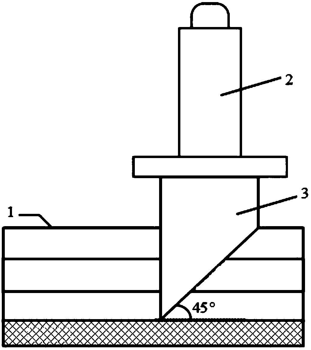
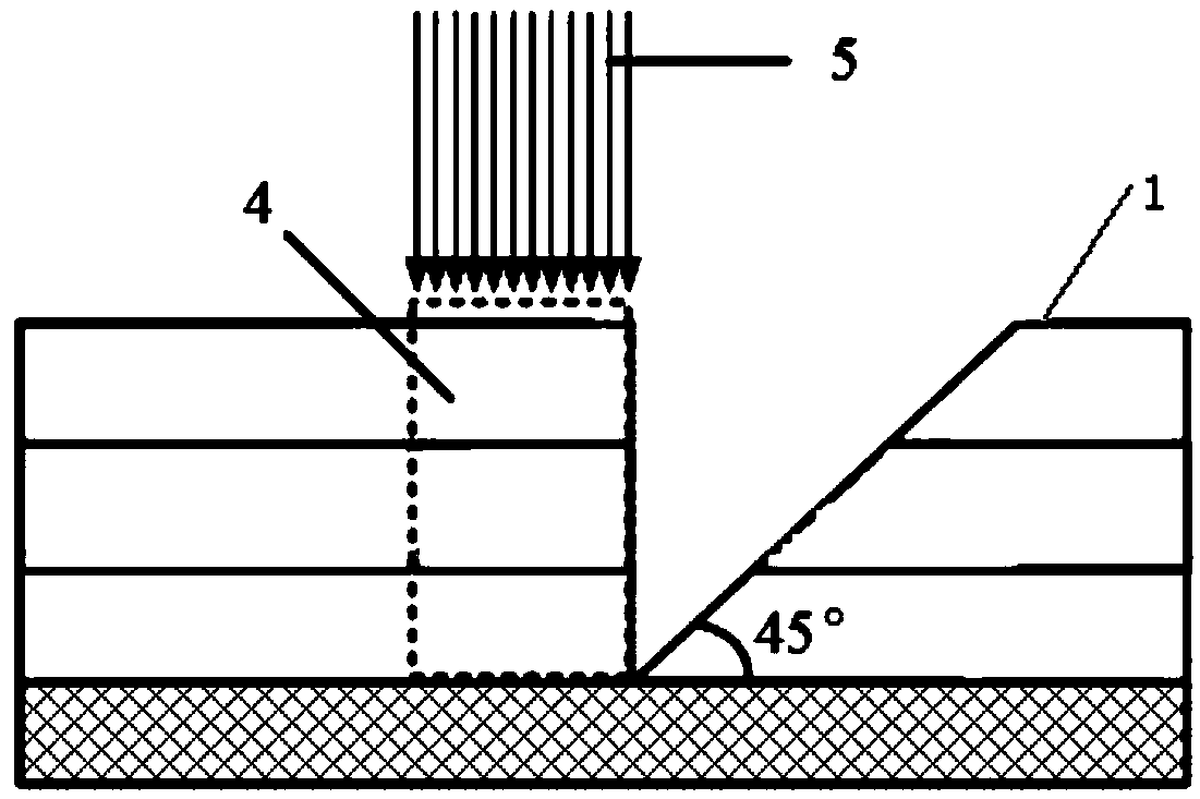
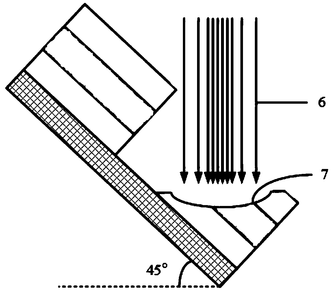
[0027] A method for preparing a concave mirror on a polymer optical waveguide, comprising the following steps: Step 1, using a V-shaped diamond knife to cut the optical waveguide into a V-shaped groove, one side of the V-shaped used is a 45° inclined surface, and one side is a vertical surface, Such as figure 1 As shown, the optical waveguide 1 includes four layers, which are the substrate, the lower cladding layer, the core layer and the upper cladding layer from bottom to top, and the v-shaped diamond cutter head can be cut to the lower cladding layer; step 2, using an excimer laser The vertical surface next to the v-shaped groove is one side, and the required laser energy is 5mJ to etch the cube groove. The width of the cube groove is 2 / 3-1 times the depth of the v-shaped groove, and the depth is the same as the depth of the v-shaped groove; step 3 , place the plate obliquely so that the inclined surface of the v-shaped groove is horizontal, and use a carbon dioxide laser t...

Embodiment 2

[0030] A method for preparing a concave mirror on an inorganic material (such as glass) optical waveguide, the preparation method is basically the same as that of Embodiment 1, but the laser processing parameters need to be changed. When the excimer laser etches the cube groove in step 2, the required laser energy is above 7mJ. In step 3, when the carbon dioxide laser thermally ablates the inclined surface of the V-shaped groove into a concave surface, the laser pulse energy needs to be increased to 102W, and after the inclined surface is ablated into a concave surface, it is etched with FH acid. The specific FH acid concentration and corrosion Time has a certain effect on the radius and roughness of the concave surface. Then proceed to step 4, that is, to coat the concave surface with a high reflection film to form a concave mirror.

[0031] The above specific parameter settings are only a specific example of a certain inorganic material optical waveguide, and are not limite...

Embodiment 3

[0033]Embodiment 1 and Embodiment 2 are specific instructions for etching concave surfaces of optical waveguides made of different materials. Compared with existing concave surface preparation technologies (publication numbers: CN 1272182A, CN 103395739A, paper: Design and fabrication of embedded micro-mirror inserts for out -of-plane coupling in PCB leveloptical interconnections), the present invention overcomes the deficiencies and problems in terms of materials, preparation technology, processing precision, etc., and meets the requirements of large-scale industrial production of optical backplanes. The technical invention (application number 201710076388.7) is a form of cold processing, which requires suitable mask patterns, precise parameter settings and operations. The reflective concave surface processed by this method has a relatively large roughness and requires subsequent thermal annealing process. The present invention The research group proposed to use a carbon dioxi...


PUM

PropertyMeasurementUnit
Laser wavelengthaaaaaaaaaa
Diameteraaaaaaaaaa

Abstract

The invention discloses a method for preparing a concave mirror on an optical waveguide. The method includes following steps: step 1, cutting the optical waveguide to form a v-shaped groove by employing a v-shaped diamond knife, wherein one plane of the v-shaped groove is a 45-degree inclined plane, and the other plane is a vertical plane; step 2, etching a cube groove by employing one vertical plane, close to the v-shaped groove, of an excimer laser as one side, wherein the width of the cube groove is 2/3 or once of the depth of the v-shaped groove, and the depth of the cube groove and the depth of the v-shaped groove are the same; step 3, placing a plate in an inclined manner to enable the inclined plane of the v-shaped groove to be horizontal, and performing hot working on the inclinedplane of the v-shaped groove by employing a carbon dioxide laser to enable the inclined plane to be ablated to form a recessed surface; and step 4, plating a high-reflection film on the recessed surface to form the concave mirror. According to the method, based on the fact that the diamond knife fabricates the 45-degree inclined plane, hot working is further performed by the inclined plane by employing the carbon dioxide laser, a processing process has a thermal annealing effect due to the mechanism of hot working, and the reflective concave mirror with low roughness can be obtained.

Description

technical field [0001] The invention relates to the field of micromachining and manufacture, and proposes a method for preparing a concave mirror on an optical waveguide. Background technique [0002] At present, the Optics Printed Circuit Board (OPCBs) interconnection technology based on printed circuit boards has been greatly developed, and has become a research hotspot in the field of high-end equipment information interconnection technology in recent years. It has high bandwidth, low energy consumption, and low cost. and other advantages. Divided by material type, there are two types of backplane optical waveguides, one is polymeric optical waveguides, and the other is inorganic optical waveguides, such as glass optical waveguides. [0003] Vertical coupling technology is one of the key technologies in the application of optical backplane interconnection. At present, there are many methods to realize the vertical coupling of optical fiber-optical waveguide, such as incl...

Claims


Application Information

Patent Timeline
IPC IPC(8): G02B6/136G02B6/13
CPCG02B6/13G02B6/136
Inventor 黄怿邓传鲁王廷云
Owner 苏州德睿电力科技有限公司
Why Eureka
Try Eureka