Oily pollutant ultraclean treatment process and oily pollutant ultraclean treatment equipment

A technology for processing equipment and processing technology, which is applied in the direction of water pollutants, water/sludge/sewage treatment, petroleum industry, etc., and can solve the problems of intermittent and discontinuous pyrolysis technology and equipment, high safety risks, and large emissions. Achieve the effect of improving resource utilization efficiency, improving processing efficiency and saving fuel

Pending Publication Date: 2018-08-10
大庆百世环保科技开发有限公司
View PDF6 Cites 4 Cited by
  • Summary
  • Abstract
  • Description
  • Claims
  • Application Information

AI Technical Summary

Problems solved by technology

Among them, sludge pyrolysis has been implemented worldwide, and various heating furnaces are used to separate hydrocarbons from oily pollutants. However, the pyrolysis process and equipment are intermittent and discontinuous, with low efficiency, high safety risks, and high energy consumption. Issues such as large emissions

Method used


Image

  • Oily pollutant ultraclean treatment process and oily pollutant ultraclean treatment equipment

Examples


Embodiment Construction

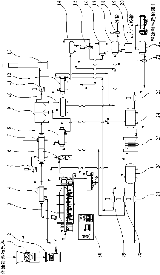
[0021] A kind of ultra-clean treatment equipment for oily pollutants of the present invention is composed of a crusher 1 and a separator. The feed port is connected to the pipeline, the gas phase outlet of the thermal desorption furnace 3 is connected to the oil-gas dust collector 6 pipeline, the oil-gas dust collector 6 is connected to the 1# oil-gas condenser 8 pipeline, and the 1# oil-gas condenser 8 is connected to the oil-gas two-phase separator 10 pipeline connection, the oil phase outlet of the oil-gas two-phase separator 10 is connected to the oil phase buffer tank 17, the gas phase outlet is connected to the 2# oil-gas condenser 12 pipeline, and the 2# oil-gas condenser 12 is connected to the three-phase separator 14 pipeline The oil phase outlet of the three-phase separator 14 is connected with the oil phase buffer tank 17, the water phase outlet is connected with the waste water tank 19, and the gas phase outlet is connected with the noncondensable gas buffer tank 16...


PUM

PropertyMeasurementUnit
particle sizeaaaaaaaaaa

Abstract

The invention provides an oily pollutant ultraclean treatment process and oily pollutant ultraclean treatment equipment, and relates to the technical field of oily pollutant ultraclean treatment. Theoily pollutant ultraclean treatment equipment comprises a crusher, a feeder, a thermal desorption furnace, a combustion fan, an oil-gas dust collector, a combustion-supporting air heater, an oil-gas two-phase separator, an oil-gas condenser, a three-phase separator, a non-condensable gas buffer tank, an oil phase buffer tank, a wastewater tank, a high temperature heat conductive oil storage tank,a generator set, a low temperature heat conductive oil storage tank and a distributed control system (DCS) intelligent autonomous control system. Oily pollutants are quantitatively conveyed to the feeder in an airtight way through a pipeline after being crushed by means of the crusher, and is then transported to a thermal desorption device, so that the labor intensity is lightened; an anaerobic thermal desorption reaction is realized by means of high temperature anaerobic operation; the non-condensable gas is recycled as fuel; the total petroleum hydrocarbon (TPH) of the treated solid phase residue is less than 0.05 percent; a closed dry slagging technology is adopted, so that clean discharge of the residue is realized; a flue gas waste heat recovery heat exchanger and the oil-gas condenser are used for realizing waste heat recovery; after the generator set is used for power generation for reuse, the recovery utilization rate of the waste heat can reach 90%.

Description

technical field [0001] The invention relates to the technical field of ultra-clean treatment of oily pollutants, in particular to a process and equipment for ultra-clean treatment of oily pollutants. Background technique [0002] Currently, a large amount of oily pollutants produced in the oil and gas production chain is an unavoidable problem in the petroleum industry. Oily pollutants have caused great harm to the environment and human health, and urgently need effective and sustainable treatment. Among them, sludge pyrolysis has been implemented worldwide, and various heating furnaces are used to separate hydrocarbons from oily pollutants. However, the pyrolysis process and equipment are intermittent and discontinuous, with low efficiency, high safety risks, and high energy consumption. Issues such as large emissions. Contents of the invention [0003] The present invention provides a process and equipment for ultra-clean treatment of oily pollutants for the above-ment...

Claims


Application Information

Patent Timeline
Patent Type & Authority Applications(China)
IPC IPC(8): C02F11/10C10G1/00C02F101/32
CPCC10G1/00C10G1/002C02F11/10C02F2101/32
Inventor 李继凤路学喜侯鹏王亚娟李林
Owner 大庆百世环保科技开发有限公司
Why Eureka
Try Eureka