
A method for growing crystal cladding in a metal tube

An in-growth, metal tube technology, applied in the directions of cladding fiber, crystal growth, single crystal growth, etc., can solve the problems of easy cracking of cladding, low sol-gel efficiency, low process qualification rate, etc., and achieve uniform refractive index distribution. Effect

Active Publication Date: 2020-11-27
TONGJI UNIV
View PDF6 Cites 0 Cited by
  • Summary
  • Abstract
  • Description
  • Claims
  • Application Information

AI Technical Summary

Problems solved by technology

[0003] However, almost all optical fibers need cladding, not only to confine the beam inside the fiber, but also to isolate the fiber from the surrounding environment to maintain the integrity of the fiber. The cladding can also be used to increase the strength of the fiber. For Silica optical fiber, the cladding of the optical fiber is made by putting the quartz tube and the quartz core together to make a prefabricated rod, which is co-drawn in the fiber drawing tower, because the quartz is heated to soften and has a state between solid and liquid. The softened state exists, the dopant that has been doped into the core will not diffuse, and the refractive index distribution in the original preform will be maintained. For the crystal fiber, since the crystal is in a liquid state after melting, it can diffuse freely, so the dopant in the core rod It is possible for the ions to diffuse into the tube rod, and the tube rod as the fiber cladding does not allow the presence of doping ions, so it is not advisable to make the crystal cladding by the method of making the quartz cladding
Units at home and abroad are trying sol-gel to make crystal optical fiber cladding, but no substantial progress has been made, because the efficiency of sol-gel is too low, and the cladding with a thickness of 5 μm can only be obtained after 10 sol-gel operations, which is far from the final The usable thickness of 200-300μm is far away, and the cladding made by sol-gel is easy to crack
At present, there is no mature process report on crystal fiber with crystal cladding at home and abroad. It is reported that the crystal core and quartz cladding are used. Good beam quality, but it does not have much effect on the amplification of laser power. The US ArmyResearch Laboratory and ONYX Optics turned to study planar guided waves---that is, the cross-section of the core rod and cladding was made square, and the core and cladding They are tightly bonded by thermal bonding, and the all-crystal fiber is truly achieved, but the qualification rate of this thermal bonding process is not high.

Method used


Image

  • A method for growing crystal cladding in a metal tube

Examples


Embodiment 1

[0023] 1. First grow Lu with a diameter of 0.3-1mm and a length of 65-120mm by the micro-drawing method 2 O 3 Crystal fiber

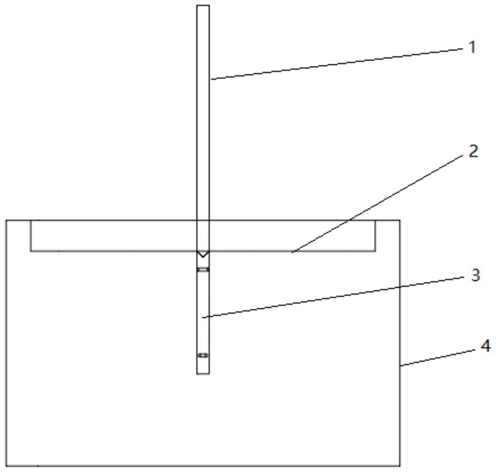
[0024] 2. Insert the optical fiber obtained in the first step into the pre-processed tungsten tube 1 (e.g. figure 1 As shown), the inner diameter of the tungsten tube 1 is slightly larger than the inner diameter of the optical fiber by 0.3-0.8mm. The lower end of the optical fiber is supported by the tungsten wire 3. The lower end 1-2mm of the tungsten tube 1 can be closed to support the tungsten wire 3 and the crystal fiber. Two small holes are made on the side wall 3-5mm above the bottom to ensure that the melt in the crucible can enter the bottom of the metal tube;

[0025] 3. Install the assembled crystal fiber, tungsten tube 1, and tungsten metal wire 3 on the seed rod of the pulling furnace;

[0026] 4. Fill the pulling furnace crucible 4 with LuScO 3 Raw materials, after installing the thermal field, close the furnace door and evacuate to within 10Pa, ...

Embodiment 2

[0029] A method for growing a crystal cladding in a metal tube includes the following steps:

[0030] S01, using micro pull-down or guided mode method, or laser heating pedestal method to obtain a crystal fiber with a diameter of 0.1 mm, wherein the micro pull-down or guided mode method, or laser heating pedestal method are methods disclosed in the existing literature;

[0031] S02, insert the crystal fiber obtained in step S01 into a metal sleeve, the core diameter of the sleeve is greater than the diameter of the fiber by 0.1 mm, the lower end of the sleeve is a metal wire with the same diameter as the crystal fiber, and the length of the metal wire is 20 mm;

[0032] S03, installing the metal sleeve, crystal fiber, and metal wire assembly obtained in step S02 on the seed rod of the crystal growth pulling furnace;

[0033] S04, heating the raw material in the crucible of the pulling furnace to melt, lower the seed rod, so that the metal wire at the lower end of the metal sleeve is pa...

Embodiment 3

[0039] A method for growing a crystal cladding in a metal tube includes the following steps:

[0040] S01: Use the micro pull-down or guided mode method, or the laser heating pedestal method to obtain a crystal fiber with a diameter of 3 mm, wherein the micro pull-down or guided mode method, or the laser heating pedestal method are methods disclosed in the existing literature;

[0041] S02, insert the crystal fiber obtained in step S01 into a metal sleeve, the core diameter of the sleeve is larger than the diameter of the fiber by 0.8 mm, the lower end of the sleeve is a metal wire with the same diameter as the crystal fiber, and the length of the metal wire is 30 mm;

[0042] S03, installing the metal sleeve, crystal fiber, and metal wire assembly obtained in step S02 on the seed rod of the crystal growth pulling furnace;

[0043] S04, heating the raw material in the crucible of the pulling furnace to melt, lower the seed rod, so that the metal wire at the lower end of the metal sleev...


PUM

PropertyMeasurementUnit
diameteraaaaaaaaaa
melting pointaaaaaaaaaa
lengthaaaaaaaaaa

Abstract

The invention relates to a method for growing crystal cladding in a metal tube. The method includes: inserting a crystal optical fiber into a metal sleeve, wherein the core diameter of the sleeve is 0.1-0.8mm larger than the diameter of the optical fiber, and the lower end of the sleeve is provided with a metal wire with the diameter being identical with the diameter of the crystal optical fiber;mounting to a crystal growth pulling furnace seed rod, heating raw materials in a pulling furnace crucible until the raw materials melt, and lowering the seed rod to allow the metal wire at the lowerend of the metal sleeve to be partially soaked into the melt so as to allow the melt to climb along gaps among the metal sleeve, the crystal optical fiber and the metal wire under a capillary effect,wherein the length of the part, exposed out of the liquid surface, of the upper end of the metal wire is 2-3mm; continuing rising the temperature of the melt in the crucible to allow the melt to fillthe gap between the metal sleeve and the crystal optical fiber; pulling the metal sleeve out of the melt in the crucible at the pulling rate of 5-10mm / h, and cooling to room temperature to obtain thecrystal optical fiber with the crystal cladding. Compared with the prior art, the method has the advantages that the crystal core can be seamlessly connected with the crystal cladding, uniform refractive index distribution can be obtained, and a high-power crystal optical fiber laser device can be obtained.

Description

Technical field [0001] The invention belongs to the technical field of crystal material preparation, and relates to a manufacturing process of a high-power fiber laser fiber and a cladding. Background technique [0002] Quartz fiber has made outstanding contributions to optical communications, and some people want to use it as a high-power laser to solve the problem of thermal effects faced by high-power lasers. Thermal effects can cause thermal depolarization and thermally induced diffraction loss, which seriously affect the laser The main performance indicators such as the output power, conversion efficiency and beam quality of the high-power laser, and even damage to the gain medium in severe cases, are the main limiting factors for the performance of high-power lasers. In order to alleviate the impact of thermal effects, technicians in related fields use gain media in the form of slats, DISKs and optical fibers to increase the surface area to volume ratio of the gain media an...

Claims


Application Information

Patent Timeline
Patent Type & Authority Patents(China)
IPC IPC(8): G02B6/02C30B15/00C30B29/24H01S3/067
CPCC30B15/007C30B29/24H01S3/06716
Inventor 徐军王东海李纳薛艳艳罗平王庆国唐慧丽
Owner TONGJI UNIV
Learn More