
Power generation system and power generation method for biomass gasification coupled coal-fired boiler

A technology for coal-fired boilers and power generation systems, which is used in gasification process, granular/powder fuel gasification, chemical industry, etc. complex problems, to achieve the effect of easy large-scale amplification, preventing low-temperature ash accumulation and slagging, and saving coal combustion

Pending Publication Date: 2018-08-28
SHANGHAI BOILER WORKS
View PDF0 Cites 7 Cited by
  • Summary
  • Abstract
  • Description
  • Claims
  • Application Information

AI Technical Summary

Problems solved by technology

However, the project started construction in 2008, and it has not been in normal operation for about 8 years, mainly due to the large difference between biomass raw materials and coal, the complex fluidized bed gasification process, the harsh conditions of the crude gas cooling process, and the difficulty in process control. Large, tar precipitation during the cooling process of biomass gasification crude gas affects the normal operation of heat exchange equipment and fans, and the stability and reliability of the system need to be further improved

Method used


Image

  • Power generation system and power generation method for biomass gasification coupled coal-fired boiler
  • Power generation system and power generation method for biomass gasification coupled coal-fired boiler
  • Power generation system and power generation method for biomass gasification coupled coal-fired boiler

Examples


Embodiment Construction

[0037] Below in conjunction with specific embodiment, further illustrate the present invention.

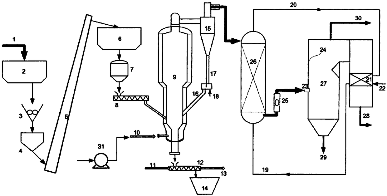
[0038] figure 1 A schematic diagram of a biomass gasification coupled coal-fired boiler power generation system provided for this example, said biomass gasification coupled coal-fired boiler power generation system mainly includes a biomass storage and delivery unit, a biomass circulating fluidized bed gasification unit, a biomass Material high temperature gas waste heat recovery unit, crude gas metering air supply unit and supporting combustion unit and other equipment.

[0039] Such as figure 1 As shown, the biomass storage and transportation unit mainly includes biomass storage bin 2, cutting crusher 3, hopper 4, conveyor belt 5, raw material bin 6, feeding bin 7, frequency conversion screw feeder 8 and supporting pipeline instruments. The cutting and breaking machine 3 is set under the biomass storage bin 2, the hopper 4 is set under the cutting and breaking machine 3, and t...


PUM


Abstract

The invention provides a power generation system for a biomass gasification coupled coal-fired boiler. The power generation system comprises a biomass storage conveying unit, a biomass circulating fluidized bed gasification unit, a biomass high-temperature fuel gas waste heat recovering unit, a crude gas metering air supply unit and a matched combustion unit, wherein the biomass storage conveyingunit is used for finishing and storing collected biomass raw materials, as well as cutting, breaking and discharging the biomass raw materials; the biomass circulating fluidized bed gasification unitis used for gasifying cut and broken biomass particles into crude gas; the biomass high-temperature fuel gas waste heat recovering unit is used for adopting boiler feed water from a high-temperature economizer of a coal-fired boiler as a cooling medium and cooling the crude gas; the crude gas metering air supply unit and the matched combustion unit are used for feeding the cooled crude gas into the coal-fired boiler for combusting in a metering manner. The invention also provides a power generation method for the biomass gasification coupled coal-fired boiler. By coupling biomass gasification,waste heat recovery and combustion, the power generation system and the power generation method disclosed by the invention have the advantages that indirect power generation of biomass is realized, the biomass is efficiently utilized while fire coal is saved, NOx emission of the coal-fired boiler is reduced and a broad application prospect is realized.

Description

technical field [0001] The invention relates to a biomass gasification coupled coal-fired boiler power generation system and a process method thereof, belonging to the technical field of biomass treatment. Background technique [0002] The total amount of biomass produced in the world every year is second only to the total amount of fossil energy consumed each year, and it is a renewable and clean resource. Energy issues and environmental issues are two major issues facing the world. With the increasing consumption of fossil energy such as conventional energy coal, oil, and natural gas, these energy sources are gradually consumed, and the impact of traditional fossil energy consumption on the environment is gradually emerging. , the El Niño phenomenon frequently exacerbates the impact, the polar glaciers melt, and the ecological environment suffers unprecedented challenges. The Chinese government has promised the world that by 2020 non-fossil energy will account for about 1...

Claims


Application Information

Patent Timeline
IPC IPC(8): C10J3/48C10J3/72C10J3/86
CPCC10J3/485C10J3/72C10J3/86C10J2300/0916C10J2300/0956C10J2300/1671Y02P20/129Y02P20/10
Inventor 倪建军池国镇张毓姝陈子珍
Owner SHANGHAI BOILER WORKS
Learn More