Municipal activated sludge treatment catalyst body, sludge treatment system and sludge treatment method

A technology of activated sludge and treatment method, applied in sludge treatment, water/sludge/sewage treatment, dehydration/drying/concentrated sludge treatment, etc., can solve the problem of high water content, difficult sludge, and slow hydrolysis process rate and other problems, to achieve the effect of not easy to wear, improve service life, and promote rapid movement

Active Publication Date: 2018-09-07
成都承宏机电有限公司
View PDF6 Cites 7 Cited by
  • Summary
  • Abstract
  • Description
  • Claims
  • Application Information

AI Technical Summary

Problems solved by technology

In the whole process of sludge anaerobic digestion, the rate of hydrolysis process is slow, which is the rate-limiting stage, resulting in the disadvantages of long residence time of sludge anaerobic digestion (generally more than 30 days) and low gas production.
[0006] The main reason for the high water content of the sludge after mechanical dehydration is that the biological cells and colloids in the sludge contain a large amount of "intracellular water" (accounting for 70% of the total water content) which cannot be fully squeezed out by the pressure of traditional mechanical dehydration. When the moisture content of the mud is between 60% and 65%, it is viscous, and the water molecules are wrapped by a layer of colloid. This area is called the "viscose phase area" of the sludge, which is the most difficult stage of sludge dehydration. The traditional mechanical dehydration method is difficult to further remove

Method used


Image

  • Municipal activated sludge treatment catalyst body, sludge treatment system and sludge treatment method
  • Municipal activated sludge treatment catalyst body, sludge treatment system and sludge treatment method
  • Municipal activated sludge treatment catalyst body, sludge treatment system and sludge treatment method

Examples


Embodiment

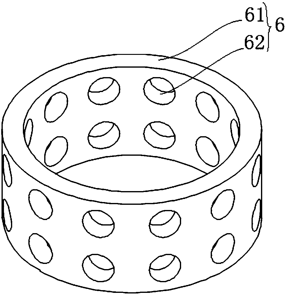
[0044] refer to image 3 As shown, the municipal activated sludge treatment catalytic body, the catalytic body 6 is a carrier made of stainless steel, the surface of the stainless steel material is preferably but not limited to a metal layer of platinum oxide, and rhodium oxide, palladium oxide, iridium oxide, etc. precious metal oxides. Platinum is solidified on the surface of the stainless steel material by sintering or sputtering. The stainless steel material structure is preferably a circular tube body 61, a plurality of through holes 62 are provided on the tube wall of the tube body 61, the diameter of the tube body 61 is 30mm, the wall thickness of the tube body is 1.5mm, and the length of the tube body is 25mm. The diameter of the through hole is 5mm. The diameter, wall thickness, and length of the pipe body 61 are determined by the catalytic body 6 being able to enter the reactor under the impact force of the mixture in the reactor, and the mixture forms a continuous...


PUM

PropertyMeasurementUnit
diameteraaaaaaaaaa
thicknessaaaaaaaaaa
lengthaaaaaaaaaa

Abstract

The invention discloses a municipal activated sludge treatment catalyst body, a sludge treatment system and a sludge treatment method, belonging to the technical field of municipal engineering sludgetreatment. The catalyst body takes a stainless steel material as a carrier; the surface of the stainless steel material is loaded with a noble metal oxide layer; noble metal oxides are solidified on the surface of the stainless steel material by sintering or sputtering; the structure of the stainless steel material is a circular, rectangular or polygonal tube body, and a plurality of through holesare formed in the wall the tube body; the noble metal oxides are any one or more of a platinum oxide, a rhodium oxide, a palladium oxide and an iridium oxide. The plurality of through holes are formed in the side wall of the catalyst body, so that a larger specific surface area can be obtained, the contact area between sludge and the catalyst body is enlarged, and the reaction time is further shortened; furthermore, the self weight of the catalyst body is further reduced, so that the speed, at which the catalyst body moves up and down as rolling over along with a mixture in a reactor, is accelerated, and the sludge treatment efficiency is increased.

Description

technical field [0001] The invention relates to the technical field of municipal engineering sludge treatment, in particular to a municipal activated sludge treatment catalytic body, a sludge treatment system and a sludge treatment method. Background technique [0002] At present, the activated sludge method is a treatment method commonly used in urban domestic sewage treatment plants, and it has a history of nearly a hundred years. A large amount of sludge will be generated during the activated sludge treatment process. The sewage treatment plant needs to concentrate, dehydrate and digest the generated sludge. The treated sludge needs to be landfilled, anaerobic digestion or Incineration disposal, such a cumbersome sludge treatment and disposal process requires very high costs as a support, which can account for 25% to 60% of the total operating costs of the entire sewage treatment plant, and the cost is very high, but the post-processing of the existing technology uses Th...

Claims


Application Information

Patent Timeline
Patent Type & Authority Applications(China)
IPC IPC(8): C02F11/06C02F11/12C02F11/14C02F11/00
CPCC02F11/00C02F11/06C02F11/12C02F11/122C02F11/14C02F2303/04C02F2305/023
Inventor 范宏梁明杨锦梁
Owner 成都承宏机电有限公司
Why Eureka
Try Eureka