Phase change fracturing method

A fracturing fluid and non-phase-change technology, applied in the field of fracturing, can solve problems such as gel breaking, fracturing failure, and increased residue content, and achieve the effects of good fluidity, improved toughness, and shortened time

Active Publication Date: 2018-09-21
PETROCHINA CO LTD
View PDF7 Cites 23 Cited by
  • Summary
  • Abstract
  • Description
  • Claims
  • Application Information

AI Technical Summary

Problems solved by technology

[0007] (1) If the fracturing fluid is not completely broken and flowed back, it will seriously damage the conductivity of the formed artificial fractures and reduce the permeability of the matrix near the fractures;
[0008] (2) In the face of high-temperature deep wells, in order to maintain the sand-carrying ability of fracturing fluid at high temperature, the concentration of additives such as guar gum and cross-linking agent is increased, which leads to further increase of residue content and frictional resistance, which further leads to fracture. Glue, flowback and other issues;
[0009] (3) For sand fracturing, in order to pursue high conductivity, high sand ratio is used to add sand, which may easily lead to sand plugging and other accidents;
[0010] (4) With the prolongation of production time after construction, problems such as embedment, deformation and backflow of conventional proppants such as ceramsite and quartz sand will cause a significant decrease in conductivity after compression, and the effective period of construction will be greatly shortened
For this reason, technicians have developed a phase-change fracturing method that does not use solid-phase proppants. However, in the existing process, due to the need for phase-change reactions to be carried out at a certain temperature, the phase-change material liquid is injected The temperature behind the formation can only rely on the formation temperature to rise slowly, which makes it difficult for the ground to effectively control the time and progress of the phase change reaction, which may easily lead to poor results or even failure of fracturing

Method used


Image

  • Phase change fracturing method
  • Phase change fracturing method
  • Phase change fracturing method

Examples


Embodiment 1

[0076] This embodiment provides a phase change material liquid.

[0077] The preparation process of the phase change material solution provided in this embodiment is as follows:

[0078] First take 50g of xylene, then add 40g of 2,4-diamino-6-diallylamino-1,3,5-triazine, 30g of dicyclopentadiene resin, 0.5g of hydroxypropyl methylcellulose, twelve Sodium alkyl sulfate 0.5g, phosphoric acid 0.5g, calcium chloride 0.5g, dibenzoyl peroxide 1g. All are placed in the flask, stirred at room temperature to complete the preparation of the phase change material liquid (the prepared phase change material liquid is denoted as HPP 1 ).

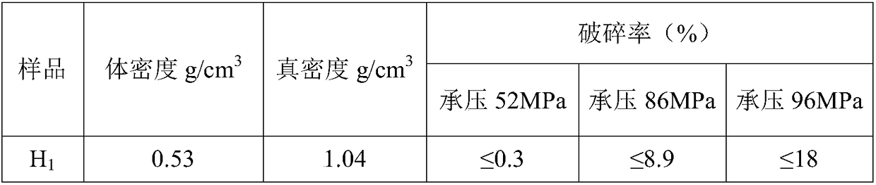
[0079] The phase change material solution in this example was placed in a constant temperature oil bath, and the temperature was raised to 90 ° C for 1 hour to react, and beads and massive solid phases appeared, that is, solid phase proppant (denoted as H 1 ). It can be seen that the phase change material liquid provided in this embodiment can realize...

Embodiment 2

[0084] This embodiment provides a phase change material liquid.

[0085] The preparation process of the phase change material solution provided in this embodiment is as follows:

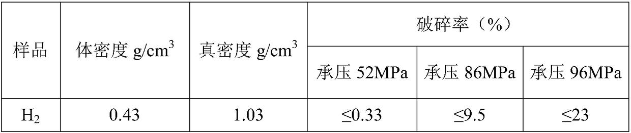
[0086] First take 50g of xylene, then add 40g of propenyl substituted triazine, 30g of dicyclopentadiene resin, 0.7g of polyvinyl alcohol, 0.3g of sodium dodecylsulfonate, 0.5g of phosphoric acid, 0.5g of calcium chloride, peroxide Dibenzoyl 1g, ammonium bicarbonate 5g. All placed in a flask, stirred evenly at room temperature to complete the underground phase change material liquid HPP 3 preparation.

[0087] The phase-change material liquid N in this example was placed in a constant temperature oil bath, and the temperature was raised to 100°C for 0.5 hours to react. Bead-like and block-like solid phases appeared, that is, solid-phase proppant (denoted as H 2 ). It can be seen that the phase change material liquid N provided in this embodiment can realize the transition from liquid phase to sol...
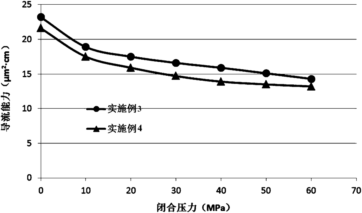
Embodiment 3

[0095] This embodiment provides a phase change fracturing method.

[0096] Taking the ground outcrop as the experimental material, the indoor experiment simulation is carried out by using the core fracture conductivity simulation device. First cut the outcrop into rock slabs (8cm×5cm×1.75cm) according to equipment requirements, and put the two rock slabs into the core holder. To simulate the fracturing construction process, at a temperature of 80°C, the injection pressure and confining pressure were changed to carry out the experiment on the conductivity of rock slab fractures.

[0097] According to "inject fracturing fluid A agent → inject non-phase-change material liquid M (phase-change material liquid M is added with the first heat-generating reagent B) and phase-change material liquid N from two acid injection tanks simultaneously → inject the second Heat-generating reagent C→inject displacement fluid to displace the reagent in the pipeline into the slab→suppress pressure...


PUM

PropertyMeasurementUnit
degree of substitutionaaaaaaaaaa

Abstract

The invention provides a phase change fracturing method. The method includes the following steps that a fracturing fluid is injected into a stratum to generate cracks in the stratum, and injection ofthe fracturing fluid is stopped after the to-be-generated cracks reach preset requirements; a phase change reaction liquid and a time delay heat generating agent which can be subjected to a phase change reaction at preset temperature are injected into the stratum; after injection of the phase change material liquid is substantially completed, the time delay heat generating agent exerts a heat generating action to make phase change of the phase change material liquid to complete phase change fracturing. According to the provided technical scheme, since there is no solid phase injection, not only can the friction resistance of tubular columns be effectively reduced, but also the happening time and progress of the phase change reaction can be effectively controlled due to the use of the delayheat generating agent, so that a better fracturing effect is achieved. Especially for low-temperature reservoirs, a heat generation effect of the delay heat generating agent greatly increases the rate of the phase change reaction so that the phase change material liquid can rapidly form a solid phase at a preset position, the phase change time is shortened, and the probability of successful construction is increased.

Description

technical field [0001] The invention belongs to the technical field of fracturing, and in particular relates to a phase change fracturing method. Background technique [0002] Hydraulic fracturing technology has been widely used in the development of low-permeability oil and gas fields as the main measure for oil and gas well stimulation and water well injection, and has made important contributions to the stable production of oil and gas fields. The process of hydraulic fracturing is to pump high-viscosity pre-fluid into the target reservoir to form fractures and extend them at high pressure, and then pump sand-carrying fluid mixed with proppant, which can continue to extend the fracture and carry proppant at the same time. Go deep into the fracture, and finally degrade the fracturing fluid into a low-viscosity fluid and flow back to the bottom of the well, leaving a flow channel with high conductivity formed by the proppant supporting the fracture wall in the formation, so...

Claims


Application Information

Patent Timeline
Patent Type & Authority Applications(China)
IPC IPC(8): E21B43/26C09K8/68C09K8/80
CPCE21B43/26C09K8/68C09K8/80C09K8/665C09K8/90E21B43/24E21B43/2405E21B43/2605
Inventor 余东合张以明车航宁萌萌杜娟王鹏杜光焰裴宇昕邱守美王孝超
Owner PETROCHINA CO LTD
Why Eureka
Try Eureka