
A process and method for eliminating smoke plume through flue gas reheating in combination with CO low-temperature denitration

A low-temperature denitrification and flue gas reheating technology, applied in separation methods, chemical instruments and methods, gas treatment, etc., can solve the problems of secondary pollution air preheaters, threats to the ecological environment, high biological toxicity, etc., and achieve high denitrification efficiency , avoid sulfur inactivation, the effect of simple method

Inactive Publication Date: 2018-09-25
SHANDONG UNIV
View PDF3 Cites 1 Cited by
  • Summary
  • Abstract
  • Description
  • Claims
  • Application Information

AI Technical Summary

Problems solved by technology

However, because the SCR technology uses ammonia as a reducing agent, it will cause corrosion to the pipeline. Improper control will easily cause secondary pollution caused by ammonia escape and blockage of the air preheater; most of the catalysts used are vanadium-titanium catalysts, and the biological toxicity is relatively high. High is a great threat to the ecological environment, and it is difficult to regenerate after poisoning and inactivation

Method used


Image

  • A process and method for eliminating smoke plume through flue gas reheating in combination with CO low-temperature denitration

Examples


Embodiment 1

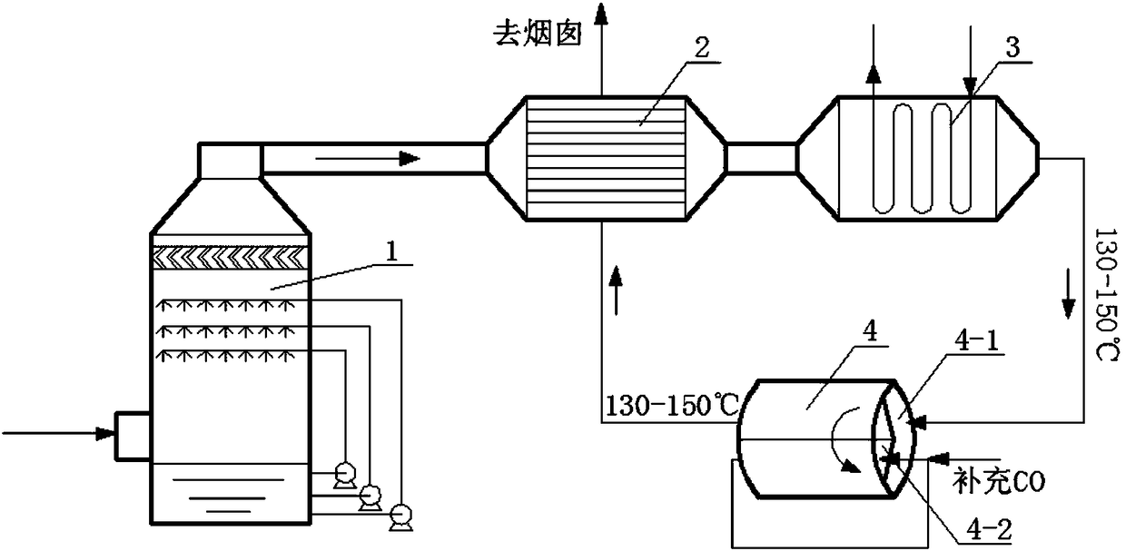
[0036]On the flue behind the wet desulfurization tower 1 of the coal-fired power plant, the gas-gas plate heat exchanger 2, the flue gas heater 3 and the rotary low-temperature denitration reactor 4 are connected in sequence. The low-temperature denitration reactor 4 is divided into nitrogen oxide adsorption Zone 4-1 and CO reduction zone 4-2. The flue gas in the flue behind the induced draft fan enters from the flue gas inlet of the wet desulfurization tower 1, removes sulfur oxides in the flue gas through wet desulfurization, and enters the gas-gas plate heat exchange from the flue gas outlet of the wet desulfurization tower 1 The heat source of gas-gas plate heat exchanger 2 comes from the flue gas at 130°C, and the wet flue gas after desulfurization is heated to 100-120°C, and the flue gas at 100-120°C enters the flue gas for heating The reactor 3 is further heated to 130-150°C. The heat source comes from high-temperature hot water at 150°C, steam turbine extraction or gas...

Embodiment 2

[0038] On the flue behind the wet desulfurization tower 1 of the coal-fired power plant, the gas-gas plate heat exchanger 2, the flue gas heater 3 and the circulating fluidized bed reactor 4 are connected in sequence, and the circulating fluidized bed reactor 4 is divided into an ascending zone The catalyst bed material is loaded in the bed, and the bed material circulates in the ascending zone and the descending zone. The flue gas in the flue behind the induced draft fan enters from the flue gas inlet of the wet desulfurization tower 1, removes sulfur oxides in the flue gas through wet desulfurization, and enters the gas-gas plate heat exchange from the flue gas outlet of the wet desulfurization tower 1 The heat source of gas-gas plate heat exchanger 2 comes from the flue gas at 130°C, and the wet flue gas after desulfurization is heated to 100-120°C, and the flue gas at 100-120°C enters the flue gas for heating The reactor 3 is further heated to 130-150°C, the heat source co...


PUM


Abstract

A process and method for eliminating smoke plume through flue gas reheating in combination with CO low-temperature denitration are disclosed. On a flue of a wet desulphurization column, a gas-gas plate-type heat exchanger, a flue gas heater and a low-temperature denitration reactor are connected in order. The low-temperature denitration reactor is a rotary low-temperature denitration reactor or acirculating fluidized bed reactor. The flue after the low-temperature denitration reactor is connected to the gas-gas plate-type heat exchanger. Large smoke fume at an outlet of a chimney is eliminated through reheating of the flue gas after the desulphurization column, nitrogen oxides in the flue gas are removed at a low temperature (130-150 DEG C) and an ultra-clean emission standard for nitrogen oxides is met. The whole process is carried out after the wet desulphurization column, thus avoiding sulfur deactivation of a catalyst. The process and the method have characteristics of simple steps, convenient operation and high practicability.

Description

technical field [0001] The invention belongs to the field of flue gas reheating and white smoke elimination, and in particular relates to a process and method for flue gas reheating and white smoke elimination in cooperation with CO low-temperature denitrification. Background technique [0002] After the cancellation of GGH, the wet flue gas of the coal-fired power plant after wet desulfurization is directly discharged into the atmosphere from the chimney. When it comes into contact with the ambient air with a lower temperature, the temperature of the flue gas decreases, and the water vapor contained in it is supersaturated and condensed, and the condensed water droplets are exposed to light Refraction and scattering occur, so that the smoke plume appears white or off-white, which is called "wet smoke plume" (commonly known as "big white smoke", "white smoke plume", "colored smoke plume", etc.), which affects the appearance of the city. my country's Shanghai, Tianjin, Zhejia...

Claims


Application Information

Patent Timeline
IPC IPC(8): B01D53/86B01D53/78B01D53/50B01D53/75B01D53/56
CPCB01D53/02B01D53/50B01D53/78B01D53/8628B01D2251/204B01D2258/0283
Inventor 马春元程星星闫敏王涛张立强付加鹏
Owner SHANDONG UNIV
Learn More