Method for increasing tensile strength of high-entropy alloy with face-centered cubic structure

A high-entropy alloy, face-centered cubic technology, applied in metal material coating process, liquid chemical plating, coating, etc., can solve problems such as large plasticity and low strength

Inactive Publication Date: 2018-11-06
TAIYUAN UNIV OF TECH
View PDF3 Cites 3 Cited by
  • Summary
  • Abstract
  • Description
  • Claims
  • Application Information

AI Technical Summary

Problems solved by technology

However, high-entropy alloys with a face-centered cubic structure often exhibit low strength and large plasticity, which limits their application as engineering materials to a certain extent.

Method used


Image

  • Method for increasing tensile strength of high-entropy alloy with face-centered cubic structure
  • Method for increasing tensile strength of high-entropy alloy with face-centered cubic structure
  • Method for increasing tensile strength of high-entropy alloy with face-centered cubic structure

Examples


Embodiment 1

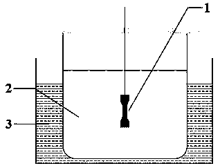
[0030] The invention breaks through the traditional method of improving the strength of the high-entropy alloy by changing its structure, and is also different from the concept of general composite materials (the volume fraction of the coating layer is very small), and has little influence on the size and shape of the high-entropy alloy matrix influences. The present invention adopts the method of chemical deposition, and coats a layer of high-strength Ni-P amorphous alloy on the surface of the high-entropy substrate to form a high-entropy alloy / Ni-P amorphous composite material, so as to improve the tensile strength of the high-entropy alloy. purpose of strength. Next, explain in detail:

[0031] The first step is the preparation of electroless plating solution, and the process formula of each component is as follows:

[0032] Nickel Sulfate (NiSO 4 •6H 2 O) 25g / L

[0033] Sodium hypophosphite (NaH 2 PO 2 •H 2 O) 25g / L

[0034] Citric acid (C 6 h 8 o 7 •H 2 O) 20...

Embodiment 2

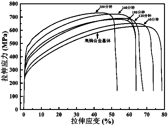
[0059] In the case of maintaining the high-entropy alloy matrix and other process conditions in the above-mentioned Example 1, in order to obtain coatings with different phosphorus contents, and study the influence of coatings with different phosphorus contents on the mechanical properties of composite materials, the reducing agent was controlled in the experiment. The concentrations of sodium phosphate were 20 g / L, 25 g / L, 30 g / L and 35 g / L, respectively, while the chemical deposition time was fixed at 4 hours. When the specified time is reached, the sample is taken out, the electroless plating is stopped and the water bath is closed. Subsequently, the deposited samples at different concentrations of sodium hypophosphite were cleaned, and then the tensile mechanical properties at room temperature were tested, and compared with the mechanical properties of the uncoated high-entropy alloy substrate.

[0060] Figure 4 The tensile engineering stress-strain curves of the coating...


PUM

PropertyMeasurementUnit
yield strengthaaaaaaaaaa

Abstract

The invention discloses a method for increasing tensile strength of high-entropy alloy with a face-centered cubic structure. The method comprises the following steps of in a chemical plating solutionusing nickel sulfate as main salt, using sodium phosphate as a reducing agent, using citric acid as a complexing agent, using ammonium hydrogen fluoride and sodium hydroxide as buffer agents, using hydrofluoric acid as an accelerator and using thiourea as a stabilizer, initiating the oxidation reduction between the nickel sulfate main salt and the reducing agent under the self-catalyzing functionof nickel atoms; finally, reducing the nickel ions in the solution and the phosphor ions in phosphite radicals into corresponding ions, and co-depositing to the surface of the high-entropy matrix, soas to form a Ni-P (nickel-phosphor) noncrystalline plating layer. The method has the advantages that one layer of Ni-P noncrystalline with high strength is deposited at the surface of the matrix, so as to reach the purpose of reducing the stress value of the high-entropy marix under the condition of same strain, thereby improving the tensile strength of the whole material; the strength of the material strength shows the positive correlation along with the thickness of the thickness of a plating layer.

Description

technical field [0001] The invention relates to a method for improving the tensile strength of a high-entropy alloy with a face-centered cubic (FCC) structure, which belongs to the field of material technology research. Background technique [0002] Due to its unique structural characteristics, high-entropy alloys have many excellent properties, such as high strength, high hardness, corrosion resistance, oxidation resistance, and good wear resistance and fatigue resistance, so they have attracted widespread attention in recent years. However, high-entropy alloys with a face-centered cubic structure often exhibit low strength and large plasticity, which limits their application as engineering materials to a certain extent. So far, in order to optimize the mechanical properties of high-entropy alloys with face-centered cubic structure and expand their application fields, a lot of research and exploration have been done. For example, Wang Zhong et al. (Wang Zhong, Lin Wanming,...

Claims


Application Information

Patent Timeline
Patent Type & Authority Applications(China)
IPC IPC(8): C23C18/36C23C18/18
CPCC23C18/1803C23C18/36
Inventor 乔珺威夏志海石晓辉张敏杨慧君吴玉程
Owner TAIYUAN UNIV OF TECH
Why Eureka
Try Eureka