Reconfigurable multi-functional antenna based on distributed direct drive arrays

A driving array and multi-functional technology, applied in antennas, antenna arrays, antenna components, etc., can solve the problems of enlarged antenna space, unsuitable size, heavy antenna, etc., and achieve precise beam pointing, high antenna efficiency, and simplified complexity degree of effect

Pending Publication Date: 2018-11-06
北京神舟博远科技有限公司
View PDF0 Cites 11 Cited by
  • Summary
  • Abstract
  • Description
  • Claims
  • Application Information

AI Technical Summary

Problems solved by technology

For example, the liquid crystal metamaterial antenna of kymeta company in the United States, although this method can achieve the scanning of the main beam and the reconfigurability of the polarization, but it has too many redundant units, and only a part of it is used at a certain time radiating elements, and even then, the phase of the radiating elements used cannot be precisely controlled, making such antennas inefficient and requiring a switching time of several milliseconds, which in some applications is unacceptable
In addition, microwave PIN diodes, gallium arsenide transistors, varactor diodes and MEMS are also used as switching devices to reconfigure the antenna, but this reconfigurable ability and function are limited, especially the diode is a nonlinear element, which will produce some some intermodulation
In addition, there are also mechanical methods to change the shape of the antenna to change the radiation pattern of the antenna, but this method will increase the space occupied by the antenna and the antenna will become too heavy
[0005] Nankai University, Nanjing University of Aeronautics and Astronautics, and Xidian University have carried out research on lateral PIN solid-state plasma reconfigurable antennas, but they are all solutions based on silicon dielectric substrates. Production line capacity and silicon wafer manufacturing process limit its size and cannot be made very large; at the same time, the above scheme does not propose an innovative technical solution to independently drive a single plasma
For example, in Nankai University's "Programmable Controlled Reconfigurable Antenna Based on Grid-shaped Transverse PIN Diodes", only a group of (minimum 4, 2×2) plasmas can be used as the basic unit for antenna design and drive. All plasma units require independent power lines to be directly driven by a shared programmable voltage source, but no specific feasible process implementation is given. When the number of plasma units to be driven is large, the drive circuit design of the invention It will be very complex, with higher requirements for devices, and higher difficulty and cost of process realization; at the same time, in this design, two adjacent silicon-based plasma units in each row or column have a common P implantation area or In the N injection area, there is no isolation groove between two adjacent plasma units. If they work at the same time, they will interfere with each other and reduce the characteristics of the plasma unit. Therefore, the performance, reconfigurable accuracy and flexibility of the antenna design invention are all limited. limit

Method used


Image

  • Reconfigurable multi-functional antenna based on distributed direct drive arrays
  • Reconfigurable multi-functional antenna based on distributed direct drive arrays
  • Reconfigurable multi-functional antenna based on distributed direct drive arrays

Examples


Embodiment 1

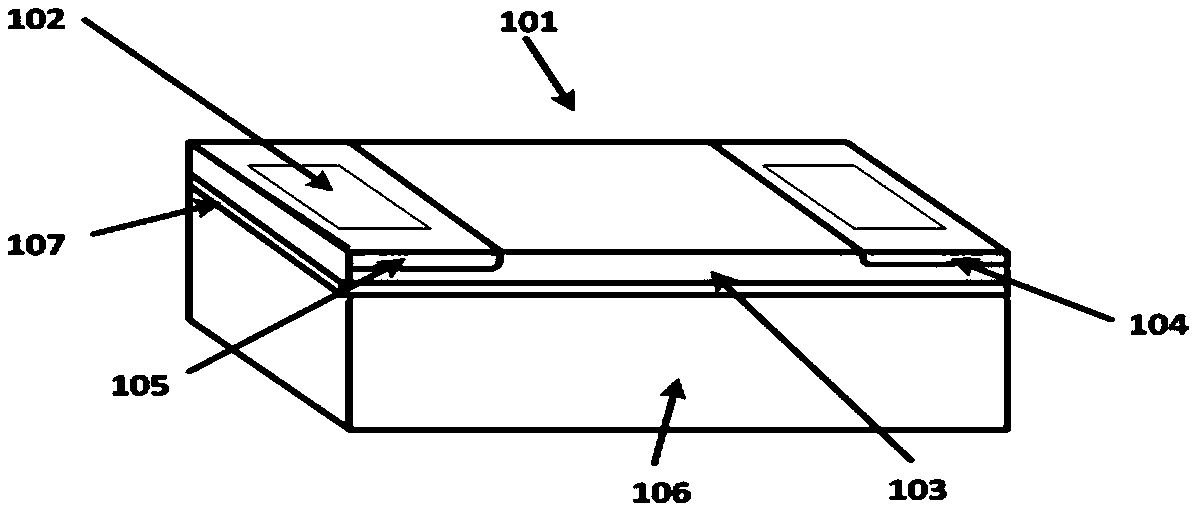
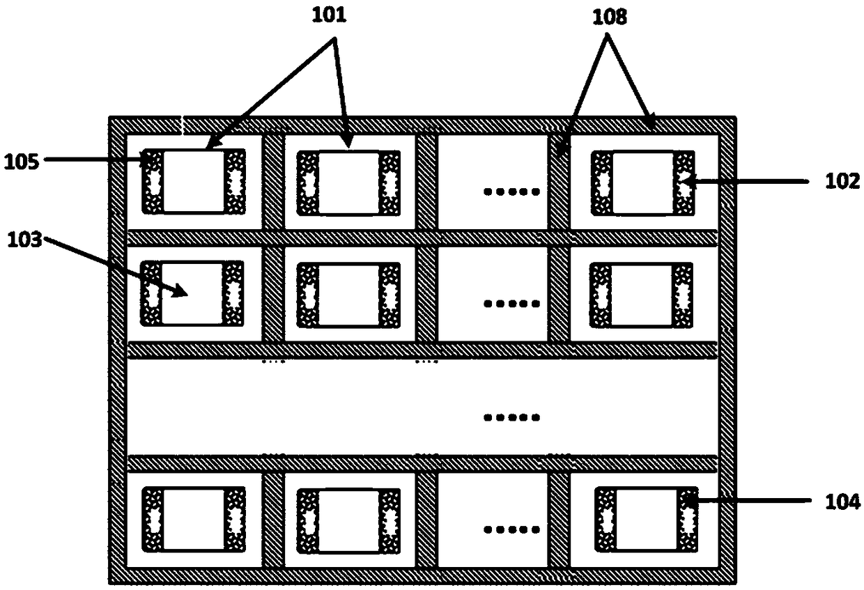
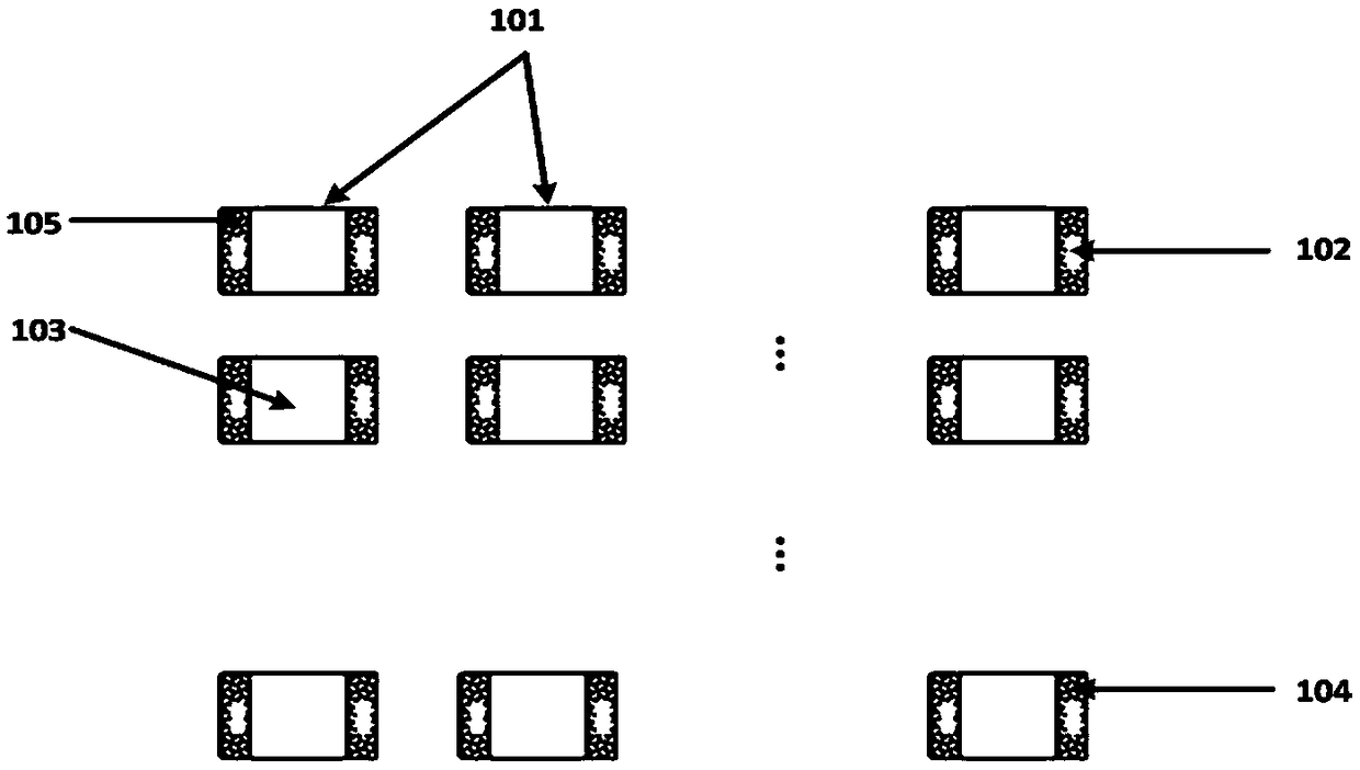
[0054] This embodiment provides a reconfigurable multifunctional antenna, the multifunctional antenna uses semiconductor plasma as a basic unit, and the multifunctional antenna includes a distributed direct drive array circuit (the distributed direct drive array circuit is based on Thin film transistor TFT matrix drive technology, the distributed direct drive array circuit has short switching time, large drive current, and simple drive mode), and the distributed direct drive array circuit controls the working state or non-working state of each of the basic units State, so as to real-time and dynamically constitute the radiation area or non-radiation area of ​​the antenna, and then control various electrical parameters of the antenna; wherein, the working state is the plasma state, and the non-working state is the non-plasma state state (insulating medium).

[0055] Using the basic unit of semiconductor plasma and the distributed direct drive array based on fast, high current a...


PUM


Abstract

The invention mainly belongs to the technical field of antennas and relates to a fast agile multi-functional planar and quasi-three-dimensional antenna, in particular to a reconfigurable multi-functional antenna. The multi-function antenna is composed of the semiconductor plasma and the fast, large current, simple TFT matrix driving technology distributed direct drive arrays integrated into silicon, glass, sapphire, silicon carbide and other planar or curved dielectric substrates, the multi-function antenna can quickly, dynamically control the shape, size and the correct position to be in of the radiating elements constituting the planar array, the antenna frequency is reconfigurable, polarization reconfigurability, beam control and gain agility reconfigurability, sidelobe position and relative level reconfigurability, and combinations of these, like a two-dimensional printer, rapidly and agilely change the antenna from one function to another, transforming a planar or quasi-three-dimensional antenna into a multi-function planar or quasi-three-dimensional antenna.

Description

technical field [0001] The invention mainly belongs to the technical field of antennas, and is related to fast agile multifunctional antennas, in particular to a reconfigurable multifunctional antenna based on a distributed direct drive array. Background technique [0002] In recent decades, reconfigurable multifunctional antennas have become a hot research field of general interest in the industry, and the increasing requirements for new wireless communication technologies and radar technologies in civilian and military fields have also promoted this research field. rapid development. Different kinds of reconfigurable technologies and implementation approaches have been studied and proved to be effective by practice. [0003] There are tens of thousands of types of antennas, and each antenna has its own unique functions and application fields. If the functions of these tens of thousands of antennas are integrated on one antenna, this antenna will become a universal antenna...

Claims


Application Information

Patent Timeline
Patent Type & Authority Applications(China)
IPC IPC(8): H01Q1/36H01Q1/38H01Q21/00H01Q23/00
CPCH01Q1/364H01Q1/38H01Q21/00H01Q23/00
Inventor 修威杨智友杨光
Owner 北京神舟博远科技有限公司
Why Eureka
Try Eureka