Fluorescence imaging method, real-time differential super-resolution microscopic imaging method and device

A fluorescent imaging and microscopic imaging technology, applied in the field of optical microscopy, to achieve the effect of large penetration depth, short life, and small light scattering

Active Publication Date: 2018-11-09
SOUTH CHINA NORMAL UNIVERSITY
View PDF6 Cites 14 Cited by
  • Summary
  • Abstract
  • Description
  • Claims
  • Application Information

AI Technical Summary

Problems solved by technology

[0005] Another object of the present invention is to provide a method for realizing real-time differential super-resolution microscopic imaging using the above-mentioned fluorescence imaging method with only a sing...

Method used


Image

  • Fluorescence imaging method, real-time differential super-resolution microscopic imaging method and device
  • Fluorescence imaging method, real-time differential super-resolution microscopic imaging method and device
  • Fluorescence imaging method, real-time differential super-resolution microscopic imaging method and device

Examples


Embodiment 1

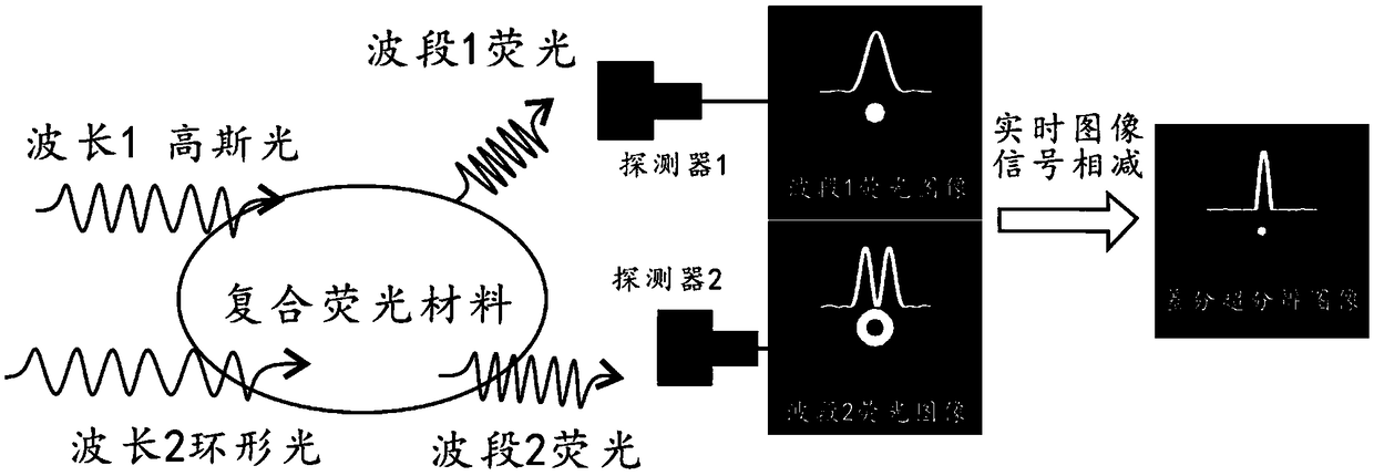
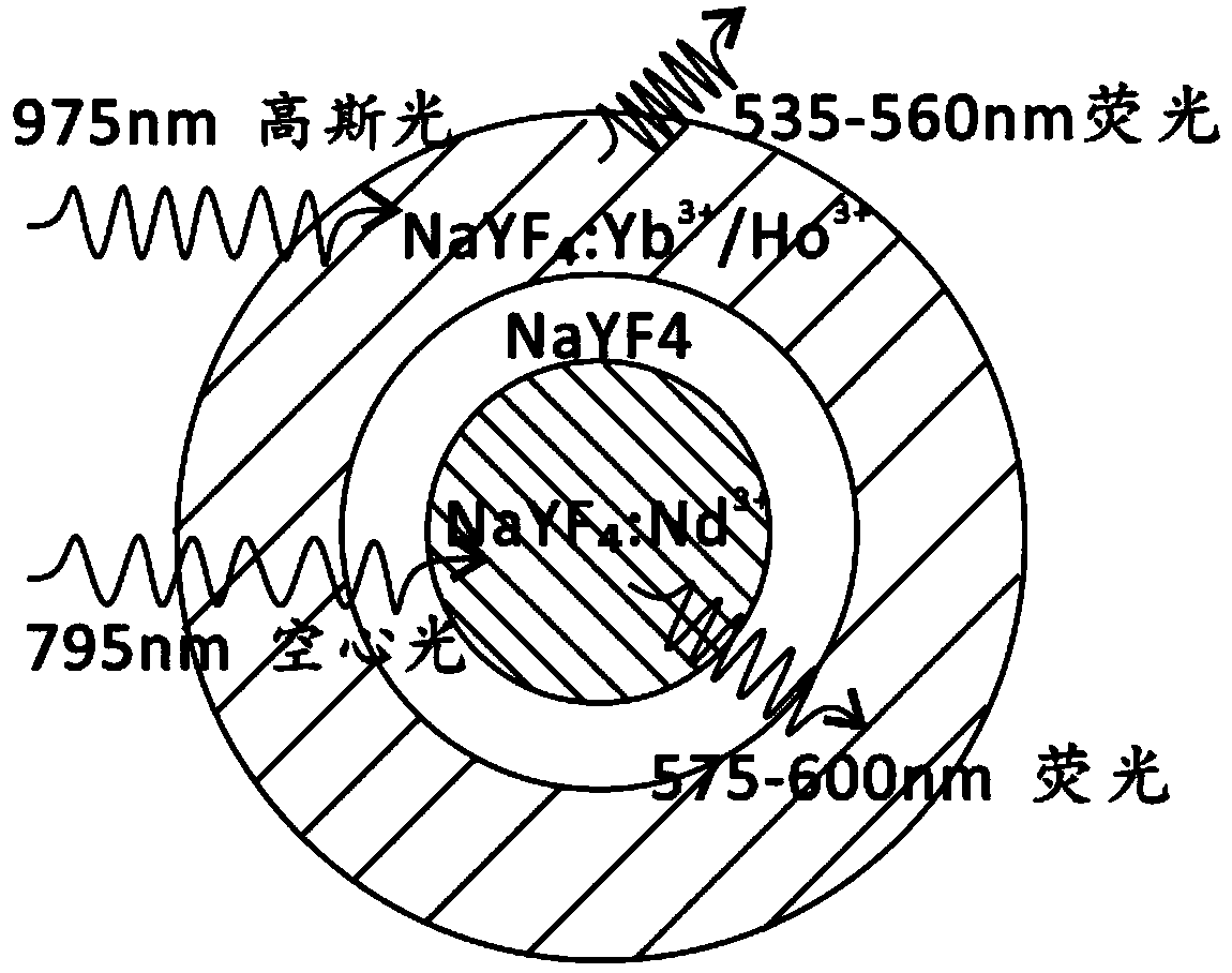
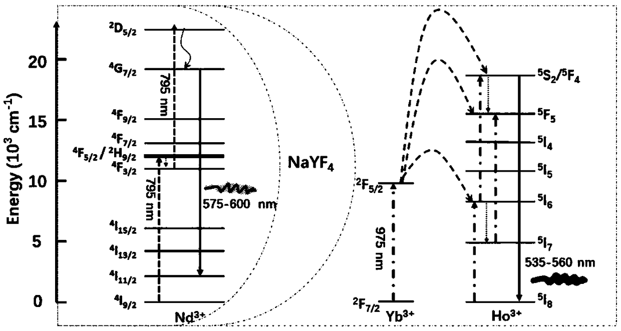
[0039] This example illustrates the implementation scheme of synthesizing two kinds of composite up-conversion nanoparticles that emit light independently. build figure 2 The three-layer core-shell structure upconversion nanoparticles NaYF 4 :Nd@NaYF 4 @NaYF 4 :Yb / Ho, able to excite Nd at 795nm 3+ Ion orange fluorescence at 575-600nm and Ho excitation at 975nm 3+ The green fluorescence of ions at 535-560nm, the schematic diagram of the energy level transition of excited fluorescence is as follows image 3 as shown, Figure 4 Fluorescence spectra for 975nm and 795nm laser excitation.

[0040] The specific steps of the material synthesis are as follows:

[0041] (1) Preparation of core NaYF4:Nd (30mol%) upconversion nanoparticles

[0042] In the oleic acid / octadecene system, add 5mL Y(CH3CO2)3 and Nd(CH3CO2)3 solutions with a concentration of 0.2mol / L and a ratio of 7:3, and raise the temperature to 150°C under open conditions for 40-50 minute, lowered to room temperat...

Embodiment 2

[0050] This example clarifies the specific implementation scheme of coupling two fluorescent molecules to composite materials. Taking DAPI coupled to AlexaFluor 568 (hereinafter referred to as AF568) as an example, DAPI can be excited by 405-nm continuous or 810-nm femtosecond laser in the 410-505nm band Fluorescence, AF568 can excite fluorescence in the 570-660nm band by 561-nm continuous or 1022-nm femtosecond laser, which meets the requirements for separation of excitation wavelength and fluorescence wavelength. Correspondingly select a suitable dichromatic mirror, such as Chroma's model 79003bs dichromatic mirror (transmission windows are 455-540nm and 570-660nm, reflection in other wavelength bands), and fluorescence filters can be applied to imaging.

[0051] The concrete implementation process of this composite material preparation is as follows:

[0052] DAPI and AF568 were respectively linked to the ends of the oligonucleotide chains by covalent bonding, and the oligo...

Embodiment 3

[0054] This example clarifies the specific implementation scheme of organic dye-coated upconversion luminescent nanoparticle composite materials, taking Alexa Fluor 532 (hereinafter referred to as: AF532) coated Yb / Tm doped nanoparticles (hereinafter referred to as: UCNP) as an example, AlexaFluor 532 Fluorescence in the 540-600nm band can be excited by a 532-nm continuous or 1064-nm femtosecond laser, and Yb / Tm doped nanoparticles can be excited by a 975-nm continuous laser in a 450-485nm band, meeting the requirements for separation of excitation wavelength and fluorescence wavelength.

[0055] The specific implementation process of composite material preparation is as follows:

[0056] (1) Alexa Fluor 532 (hereinafter referred to as: AF532) modified amino group

[0057] Weigh 0.48g (1mmol) of AF532 and 0.3g of N,N'-dicyclohexylcarboimide (DCC) and dissolve in 15ml of tetrahydrofuran (THF). At room temperature, the mixture was stirred under nitrogen protection for 24 hours....


PUM


Abstract

The invention discloses a fluorescence imaging method, which combines two fluorescent materials to prepare a composite fluorescent material. The composite fluorescent material generates two fluorescent signals with misaligned main parts under the excitation of dual-wavelength laser. During imaging, lasers of corresponding wavelengths are respectively employed to excite the composite fluorescent material to emit fluorescence of corresponding waveband. According to the fluorescence imaging method, real-time fluorescence differential super-resolution microscopic imaging can be carried out. According to the invention, two beams of wavelength lasers are modulated to form Gauss light and hollow light respectively, a laser scanning microscopic device is utilized to excite two parts of different fluorescence signals of the same composite fluorescent material respectively, further two detection channels are employed to record two pattern images, and then two channel fluorescence signals are directly subtracted to obtain a super-resolution image. According to the invention, control of light beam switching is unnecessary, super-resolution microscopic imaging can be realized only by single scanning, and the defects of high power loss of light in existing STED technology and two scanning in FED technology can be solved.

Description

technical field [0001] The invention belongs to the technical field of optical microscopy, and in particular relates to a fluorescence imaging method for realizing dual-wavelength excitation, a real-time fluorescence differential super-resolution microscopic imaging method and a microscopic imaging device by using subtraction of fluorescent signals in one scan. Background technique [0002] Stimulated emission depletion microscopy (STED) based on laser scanning imaging uses a Gaussian focused laser to scan the sample for imaging, and at the same time uses another beam of ring light to focus and deplete the fluorescence around the fluorescent spot to obtain a smaller fluorescent spot , and then scanned to obtain super-resolution fluorescence images. Due to its real-time, fast and ultra-high resolution characteristics, it is widely used in the research of subcellular structure and other cell biology problems. [0003] Single STED technology requires the application of high-po...

Claims


Application Information

Patent Timeline
IPC IPC(8): G01N21/64
CPCG01N21/6402G01N21/6428G01N21/6458
Inventor 詹求强吴秋生黄冰如周超黄文雯
Owner SOUTH CHINA NORMAL UNIVERSITY
Why Eureka
Try Eureka