Coated cutting tool with excellent chipping resistance and wear resistance

A cutting tool and surface coating technology, which is applied in the field of surface coating cutting tools, can solve the problems of reduced wear resistance, high impact and intermittent properties, and reduced toughness, and achieve excellent chipping resistance and wear resistance , Excellent cutting performance, excellent chipping resistance and wear resistance

Active Publication Date: 2020-03-13
MITSUBISHI MATERIALS CORP
View PDF4 Cites 0 Cited by
  • Summary
  • Abstract
  • Description
  • Claims
  • Application Information

AI Technical Summary

Problems solved by technology

[0011] In recent years, the high performance of cutting processing equipment has been astonishing. On the other hand, the demand for labor saving, energy saving and cost reduction of cutting processing has been strong. As a result, cutting processing has gradually become faster and more efficient. However, in the above-mentioned conventional coated tool, when the coated tool is used for cutting under general cutting conditions such as steel and cast iron, although no particular problem occurs, the coated tool When the tool is used for high-speed milling of high-hardness materials such as hardened steel, which is accompanied by high heat generation and impact and intermittent high loads are applied to the cutting edge, the occurrence of chipping and chipping cannot be suppressed , and also promotes the progress of wear, so the status quo is that the coated tool reaches the service life in a relatively short time
[0012] For example, in the conventional clad tool shown in Patent Document 1, in the (Al, Cr, Si)N layer constituting the hard coating layer, the Al component has the effect of increasing the high-temperature hardness, and the Cr component has the effect of improving the high-temperature toughness, The role of high temperature strength, and in the state of containing Al and Cr at the same time, it has the effect of improving high temperature oxidation resistance, and the Si component has the effect of improving thermoplastic deformation resistance, but it is accompanied by high heat and impact on the cutting edge. And under intermittent high-load cutting conditions, the occurrence of chipping and chipping cannot be avoided. For example, even if the improvement of high-temperature toughness and high-temperature strength is achieved by increasing the Cr content, it is also caused by the relative reduction of the Al content. Wear resistance decreases, so there is a limit to achieving both chipping resistance and wear resistance in the hard coating layer composed of (Al, Cr, Si)N layers
[0013] In addition, in the conventional coated tool shown in Patent Document 2, it is proposed to contain Cu as a component of the hard coating layer, and to improve the wear resistance by making the crystal grains finer, although the wear resistance is improved , but the chipping cannot be suppressed due to the reduction of toughness, so the tool life is short
[0014] Furthermore, in the conventional coated tool shown in Patent Document 3, by forming a composition modulation structure in which the concentration of repeated components changes in the hard coating layer, the high-temperature hardness and heat resistance can be achieved at the highest Al content point (equivalent to Cr The lowest content point) is ensured, on the other hand, the strength of the hard coating is ensured at the lowest Al content point (corresponding to the highest Cr content point) adjacent to the highest Al content point (corresponding to the lowest Cr content point), In this way, the chipping resistance and wear resistance can be ensured, and a certain degree of effect can be obtained in the cutting of general steel or alloy steel, and cast iron. However, in the cutting of high-hardness materials (for example, above HRC60), due to the effect Due to the impact and intermittent high load of the cutting edge, it cannot be said that the chipping resistance and wear resistance are not sufficient

Method used


Image

  • Coated cutting tool with excellent chipping resistance and wear resistance
  • Coated cutting tool with excellent chipping resistance and wear resistance
  • Coated cutting tool with excellent chipping resistance and wear resistance

Examples


Embodiment 1

[0122] As raw material powders, medium-coarse WC powder with an average particle size of 5.5 μm, fine-grained WC powder with an average particle size of 0.8 μm, TaC powder with an average particle size of 1.3 μm, NbC powder with an average particle size of 1.2 μm, and an average ZrC powder with a particle size of 1.2 μm, Cr with an average particle size of 2.3 μm 3 C 2 Powder, VC powder with an average particle size of 1.5 μm, (Ti, W)C [in mass ratio, TiC / WC=50 / 50] powder with an average particle size of 1.0 μm, and Co powder with an average particle size of 1.8 μm , and these raw material powders were mixed into the compounding composition shown in Table 1, and paraffin wax was further added and ball milled in acetone for 24 hours. After drying under reduced pressure, it was extruded with a pressure of 100Mpa and stamped into a prescribed shape. Various compacts, these compacts are heated to a specified temperature in the range of 1370-1470 °C at a heating rate of 7 °C / min i...

Embodiment 2

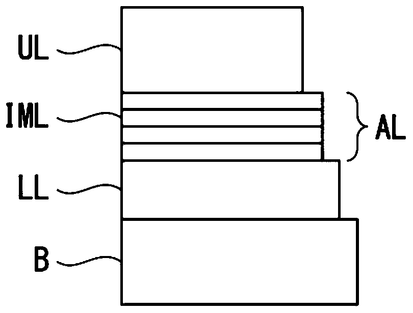
[0173] With respect to the tool substrates 1 to 3 used in Example 1, coated tools 11 to 15 of the present invention having a hard coating layer composed of a lower layer and an upper layer, and coated tools of the present invention having a hard coating layer composed of a lower layer were produced by the following method. 1. The coated tools 16 to 20 of the present invention having a hard coating layer composed of an intermediate layer and an upper layer, wherein the intermediate layer is composed of an alternate lamination structure of thin layers A and thin layers B.

[0174] (a) Tool bases 1 to 3 are installed along the outer periphery at a position spaced apart from the central axis on the turntable of the AIP device shown in FIG. A target (cathode electrode) composed of an Al-Ti-Si alloy of a given composition, and a target (cathode electrode) composed of an Al-Cr-Si-Cu alloy of a predetermined composition is arranged on the other side, in the same manner as in Example 1 ...


PUM

PropertyMeasurementUnit
thicknessaaaaaaaaaa

Abstract

In the surface-coated cutting tool, the hard coating layer includes at least an (Al, Cr, Si, Cu)N layer, which is composed of a main phase, CrSi-rich particles and Al-rich particles dispersed in the main phase. By (Al 1‑α‑β‑γ Cr α Si β Cu γ ) 1‑x N x In the case of the composition of the main phase, CrSi-rich particles and Al-rich particles, the main phase satisfies 0.15≤α≤0.40, 0.05≤β≤0.20, 0.005≤γ≤0.05, 0.45≤x≤0.60, and the The CrSi-rich particles satisfy 0.20≤α≤0.55, 0.20≤β≤0.55, 0≤γ≤0.10, 0.02≤x≤0.35, and the Al-rich particles satisfy 0.10≤α≤0.25, 0.05≤β≤0.25, 0≤γ≤ 0.10, 0.02≤x≤0.35, where α, β, γ, and x are atomic ratios, and the area ratio of CrSi-rich particles in the upper layer cross section when observing particles with a long diameter of 100 nm or more in the upper layer cross section 0.20 area % to 2.0 area %, and the area ratio of the Al-rich particles in the cross section of the upper layer is 0.50 area % to 3.0 area %.

Description

technical field [0001] The present invention relates to a surface-coated cutting tool (hereinafter referred to as a coated tool) in which a hard coating exhibits excellent chipping resistance and wear resistance during cutting of high-hardness materials such as hardened steel. And in the long-term use to play an excellent cutting performance. [0002] This application claims priority based on Patent Application No. 2016-047919 for which it applied in Japan on March 11, 2016, and uses the content here. Background technique [0003] In general, as a cladding tool, there are known indexable inserts that are detachably mounted on the front end of a turning tool for use in turning or planing of workpiece materials such as various steels or cast iron, and inserts for the workpiece materials. Drills or small drills used in drilling and cutting, end mills used in face cutting or grooving of the workpiece material, step surface processing, etc., gear cutting of the tooth profile of ...

Claims


Application Information

Patent Timeline
Patent Type & Authority Patents(China)
IPC IPC(8): B23B27/14B23B51/00B23C5/16B23F21/00C23C14/06
CPCC23C14/0021C23C14/022C23C14/0641C23C14/325C23C28/044C23C14/505C23C30/005C23C28/42C23C28/347B23B2224/00B23B2228/10B23C2224/00B23C2228/10C23C14/06B23F21/00B23B27/14B23C5/16B23B51/00B23B27/148B23B2226/125B23B2228/105
Inventor 大上强桥本达生一宫夏树
Owner MITSUBISHI MATERIALS CORP
Why Eureka
Try Eureka