
Selective Hydrogenation Method of Pyrolysis Gasoline

A pyrolysis gasoline, selective hydrogenation technology, applied in C6-C9 fractions, pyrolysis gasoline C5-C9 field, can solve the problem of catalyst activity decline

Active Publication Date: 2021-01-01
PETROCHINA CO LTD
View PDF15 Cites 0 Cited by
  • Summary
  • Abstract
  • Description
  • Claims
  • Application Information

AI Technical Summary

Problems solved by technology

The results show that the desulfurization activity of the catalyst activated at 500 °C is significantly higher than that of the catalyst activated at 600 °C, which is due to the strong interaction between the metal in the catalyst and the alumina support to form a spinel structure when activated at 600 °C lead to a significant decrease in catalyst activity

Method used


Image

  • Selective Hydrogenation Method of Pyrolysis Gasoline
  • Selective Hydrogenation Method of Pyrolysis Gasoline
  • Selective Hydrogenation Method of Pyrolysis Gasoline

Examples


preparation example Construction

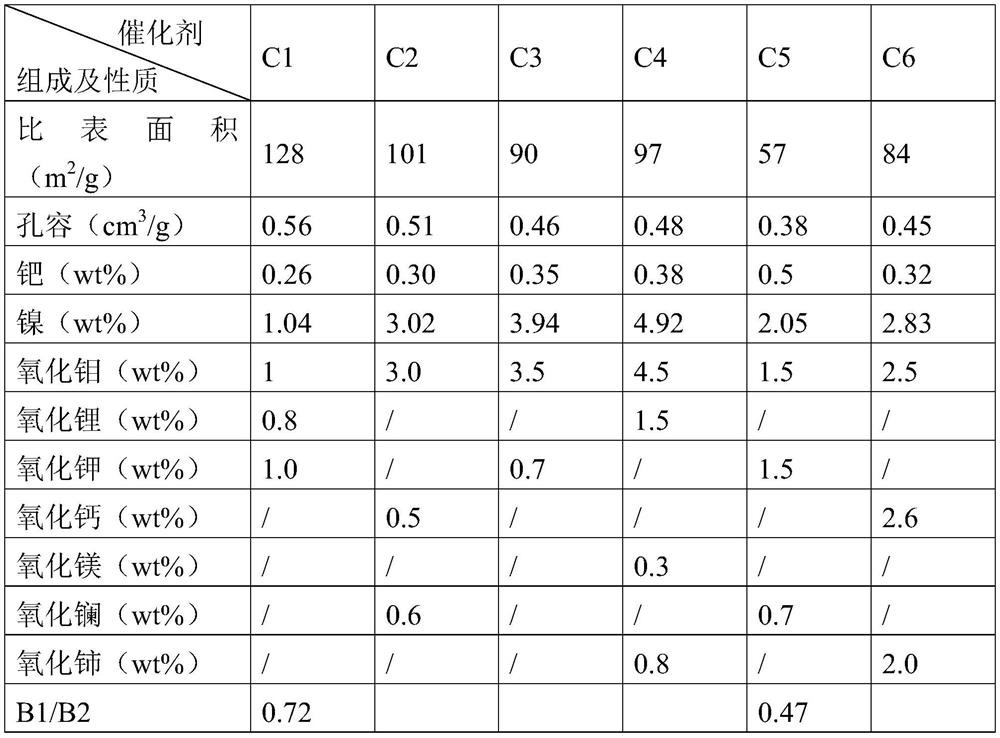
[0074] The preparation of embodiment with catalyst C1-C6:

[0075] Preparation of Catalyst C1:

[0076] Concentrate 5L to 60g Al 2 o 3 / L of sodium metaaluminate solution is put into a stainless steel container with a stirrer and the bottom of the tank can be fed with gas, and then a certain concentration of nickel nitrate solution is put into a high-position container, and the flow rate of the nickel nitrate is controlled by a peristaltic pump. The solution is added to the sodium metaaluminate solution, and a mixed gas of carbon dioxide and air is introduced into the stainless steel container at the same time, the concentration of carbon dioxide in the mixed gas is 70v%, and the flow rate is 3Nm 3 / h, the gelling temperature is 45°C, the pH value of the gelling is 9.5, after the gelling is completed, stop feeding carbon dioxide, age for 50 minutes, and the aging temperature is 45°C, filter and separate the mother liquor, wash, and dry at 120°C for 6h to obtain nickel-contai...

Embodiment 1

[0105] Put the catalyst 1 into a 250mL adiabatic fixed-bed reaction device, first carry out the reduction and activation of the catalyst, and maintain it for 8 hours under the conditions of a pressure of 2.8MPa, a bed temperature of 110°C, and a hydrogen flow rate of 125L / h to complete the reduction and activation of the catalyst.

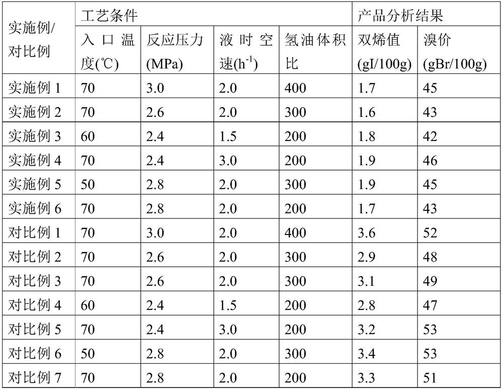
[0106] After the restore is complete, use C 5 -C 9 The distillate is the raw material, at an inlet temperature of 70°C, a reaction pressure of 3.0MPa, and a liquid hourly space velocity of 2.0h -1 1. Run for 200 hours under the condition of hydrogen oil volume ratio 400:1, sample and analyze the diene value and bromine value in the product every 24 hours, and the average value of the analysis results is shown in Table 3.

Embodiment 2

[0110] Catalyst 2 was loaded into a 250mL adiabatic fixed-bed reactor, and the catalyst reduction and activation treatment method was the same as in Example 1.

[0111] After the restore is complete, use C 5 -C 9 The distillate is the raw material, at an inlet temperature of 70°C, a reaction pressure of 2.6MPa, and a liquid hourly space velocity of 2.0h -1 1. Run for 200 hours under the condition of hydrogen oil volume ratio 300:1, sample and analyze the diene value and bromine value in the product every 24 hours, and the average value of the analysis results is shown in Table 3.


PUM

PropertyMeasurementUnit
specific surface areaaaaaaaaaaa

Abstract

The invention provides a selective hydrogenation method for pyrolysis gasoline. A single-stage adiabatic fixed-bed reactor is adopted, and the reactor is provided with a Pd-Mo-based hydrogenation catalyst. The hydrogenation process conditions are as follows: reaction temperature 30-120 DEG C, reaction pressure 2-6 MPa, airspeed 0.5-4h-1, hydrogen-to-oil volume ratio (100-600):1. One part of the hydrogenation product is used as the inner cycle of a one-stage hydrogenation reaction, and the other part is sent to a second-stage hydrogenation reactor for hydrorefining. The catalyst having a specific crystal form prepared by using a nickel-containing alumina carrier in the invention can greatly improve the dispersion and utilization rate of active metals, and the addition of selected auxiliaryactive components which are added plays a synergistic role to improve the hydrogenation activity and stability of the catalyst.

Description

technical field [0001] The present invention relates to a method for selective hydrogenation of pyrolysis gasoline fractions, in particular to a method for selective hydrogenation of pyrolysis gasoline with a Pd-Mo catalyst. The selective hydrogenation method of the present invention is especially suitable for pyrolysis gasoline C 5 -C 9 、C 6 -C 9 fraction. Background technique [0002] Pyrolysis gasoline is an important by-product of steam cracking ethylene plant, and its output is 50%-80% (mass fraction) of the ethylene production capacity. The content of aromatics is as high as 50%, and it is an important raw material for extracting aromatics. Pyrolysis gasoline also contains a large amount of unsaturated hydrocarbons (dienes, monoenes) and impurities such as sulfur and nitrogen, resulting in poor stability of pyrolysis gasoline and the formation of colloids, and these unsaturated hydrocarbons and impurities such as sulfur and nitrogen will increase significantly Redu...

Claims


Application Information

Patent Timeline
Patent Type & Authority Patents(China)
IPC IPC(8): C10G45/40B01J23/89B01J35/10
CPCB01J23/002B01J23/8993B01J35/1014B01J35/1019B01J35/1038B01J2523/00C10G45/40B01J2523/11B01J2523/13B01J2523/68B01J2523/824B01J2523/847B01J2523/23B01J2523/3706B01J2523/22B01J2523/3712
Inventor 马好文南洋胡晓丽展学成孙利民郑云弟王斌钱颖梁顺琴常晓昕黄德华彭蓉潘曦竹李平智谢培思
Owner PETROCHINA CO LTD
Learn More