
Flue gas desulfurization system

A desulfurization system and flue gas technology, applied in gas treatment, combined device, membrane technology, etc., can solve the problems of insufficiency of desulfurization process, increase of sulfur content in coal combustion, serious equipment loss, etc., to maintain speed and increase contact area, the effect of reducing corrosion

Inactive Publication Date: 2018-11-30
百色皓海碳素有限公司
View PDF4 Cites 2 Cited by
  • Summary
  • Abstract
  • Description
  • Claims
  • Application Information

AI Technical Summary

Problems solved by technology

[0002] Petroleum coke components are hydrocarbons, containing 90-97% carbon, 1.5-8% hydrogen, and nitrogen, chlorine, sulfur and heavy metal compounds. Petroleum coke is calcined to produce sulfur dioxide, nitrogen, oxygen, carbon monoxide, carbon dioxide, Hydrocarbons and nitrogen oxides, etc. Part of the sulfur dioxide and dust in the flue gas are not purified and discharged from the chimney of the calcination plant, which affects the environment
[0003] With the continuous improvement of my country's sulfur dioxide emission standards, and the sulfur content of coal combustion has also increased compared with before, the existing desulfurization process can no longer meet the relevant requirements
Furthermore, in the existing desulfurization process, due to the corrosion in the desulfurization reaction, the equipment loss is relatively serious, especially the accessories in the reaction system, which generally need to be replaced every 3 to 5 years
In addition, a large amount of water is required in the process of desulfurization reaction, and a large amount of water is also required in the cleaning and maintenance of equipment. Most of the waste water obtained in the desulfurization process in the prior art will be wasted

Method used


Image

  • Flue gas desulfurization system
  • Flue gas desulfurization system
  • Flue gas desulfurization system

Examples


Embodiment Construction

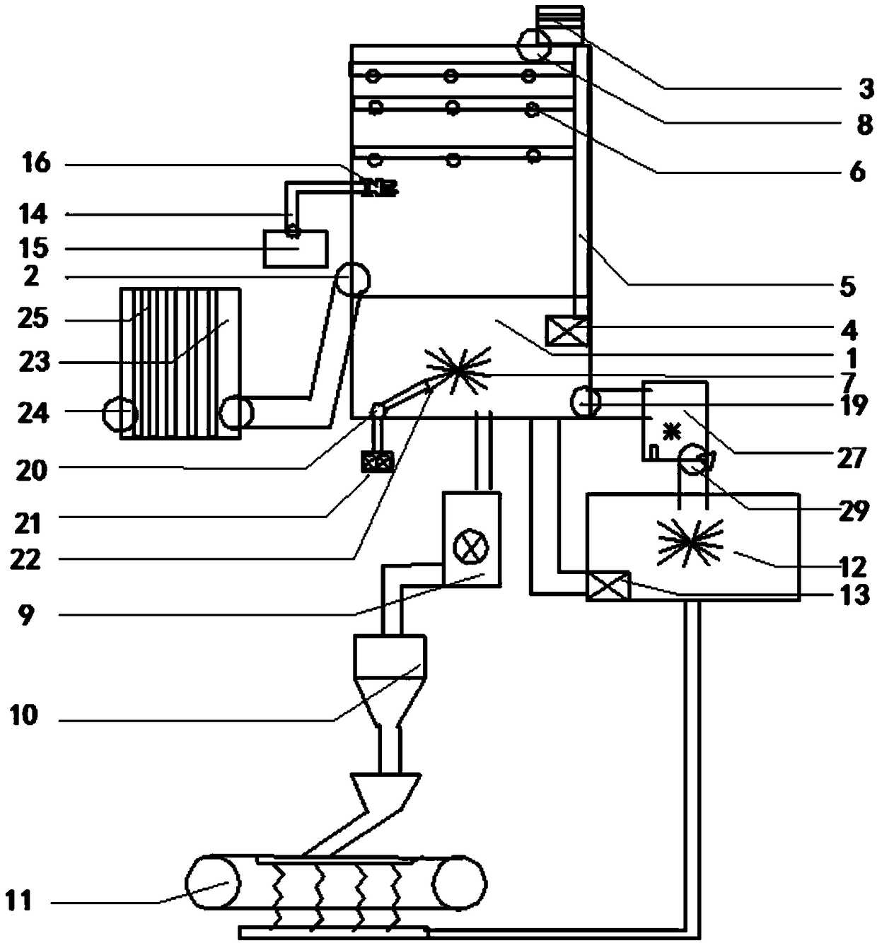
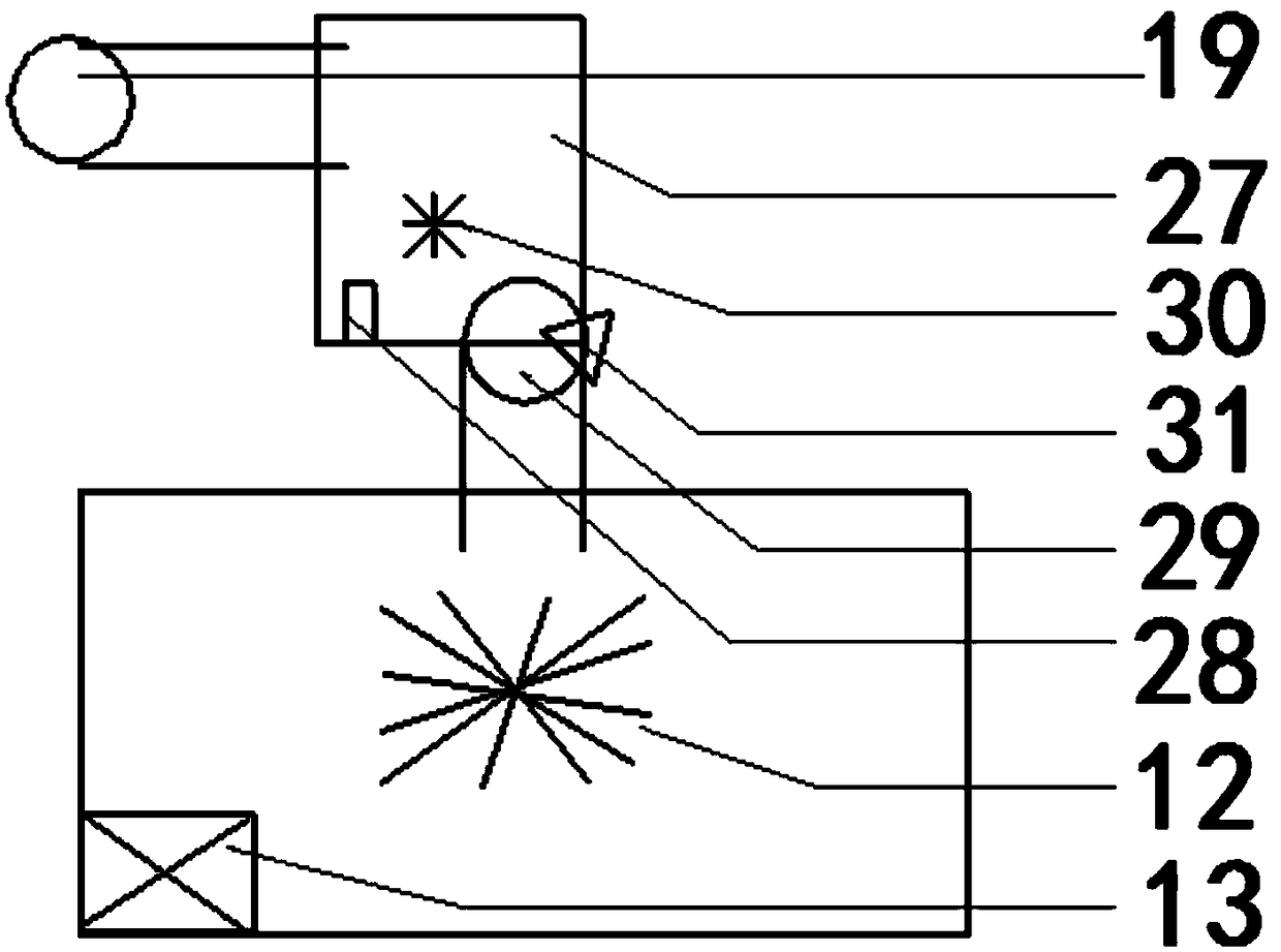
[0031] A flue gas desulfurization system, comprising:

[0032]An absorption tower, which includes a slurry tank arranged at the bottom of the absorption tower, a flue gas inlet for passing flue gas into the absorption tower, a spray device arranged above the flue gas inlet, and a Smoke outlet; the spraying device includes: a circulation pump connected to the slurry pool, a delivery pipe connected to the circulation pump and an atomizing nozzle connected to the delivery pipe, the circulation pump is arranged in the slurry pool, the The first end of the delivery pipe communicates with the circulating pump, the second end is attached to the inner wall of the absorption tower and extends upward to the top of the absorption tower, and the second end of the delivery pipe is provided with a plurality of branches, so The branch is arranged along the inner wall of the absorption tower, the atomizing nozzle is arranged on the branch and the atomizing nozzle is vertically directed to the...


PUM


Abstract

The invention discloses a flue gas desulfurization system. The flue gas desulfurization system comprises an absorption tower, a wet type electric dust collector, a dehydrating unit and a circulating unit, wherein the absorption tower further comprises a slurry tank which is arranged at the bottom layer of the absorption tower, a flue gas inlet for introducing flue gas into the absorption tower, aspraying device arranged above the flue gas inlet, and a flue gas outlet which is formed in the top of a desulfurization tower. Through the absorption effect of the absorption tower, further dust removal is performed through the wet type electric dust collector, so that a sulfur component and other harmful components in the flue gas are removed, and a second product generated by absorption effectof the absorption tower is processed. Compared with the prior art, the flue gas desulfurization system can improve desulfurization efficiency, reduces corrosion loss in desulfurization reaction, can recycle wastewater generated in a recycling process, and is environmentally friendly and energy-saving.

Description

technical field [0001] The invention belongs to the technical field of flue gas desulfurization, and in particular relates to a flue gas desulfurization system. Background technique [0002] Petroleum coke components are hydrocarbons, containing 90-97% carbon, 1.5-8% hydrogen, and nitrogen, chlorine, sulfur and heavy metal compounds. Petroleum coke is calcined to produce sulfur dioxide, nitrogen, oxygen, carbon monoxide, carbon dioxide, Hydrocarbons, nitrogen oxides, etc., part of the sulfur dioxide and dust in the flue gas are not purified and discharged from the chimney of the calcination plant, which affects the environment. [0003] With the continuous improvement of my country's sulfur dioxide emission standards, and the sulfur content of coal has increased compared with before, the existing desulfurization process can no longer meet the relevant requirements. Furthermore, in the existing desulfurization process, due to the corrosion in the desulfurization reaction, th...

Claims


Application Information

Patent Timeline
Patent Type & Authority Applications(China)
IPC IPC(8): B01D53/50B01D53/78B01D50/00
CPCB01D50/00B01D53/501B01D53/73B01D2251/404B01D2251/606B01D2258/0283
Inventor 陆剑韦瑞从黄三财徐赋曹建富陈朝永黄丽梅
Owner 百色皓海碳素有限公司
Learn More