
Treatment system for chromium-containing dyeing wastewater and implementation method thereof

A dyeing wastewater and treatment system technology, applied in the field of chromium-containing dyeing wastewater treatment system, can solve the problems of secondary pollution, complex operation and management, large amount of sludge, etc., and achieve strong impact load resistance, high system stability, The effect of high processing efficiency

Pending Publication Date: 2018-12-04
深圳市世清环保科技有限公司
View PDF0 Cites 4 Cited by
  • Summary
  • Abstract
  • Description
  • Claims
  • Application Information

AI Technical Summary

Problems solved by technology

Among them, the chemical method needs to add an excessive amount of chemicals, which is easy to cause secondary pollution, and produces a large amount of sludge
The ion exchange method uses polymer synthetic resin to exchange chromium in wastewater, which has high cost, complicated operation and management, and difficult resin regeneration and short service life.
Membrane separation methods include electrodialysis, reverse osmosis, and electrodeionization. These methods currently have problems with membrane life and cost, and are still in the research and trial stage. Electrolysis is because of its small size, small footprint, low power consumption, and convenient management , good effect and other characteristics are widely used, but it is difficult to meet the discharge standard by purely using electrolysis technology to treat chromium-containing wastewater. For wastewater with low chromium concentration, the energy consumption will rise linearly.

Method used


Image

  • Treatment system for chromium-containing dyeing wastewater and implementation method thereof
  • Treatment system for chromium-containing dyeing wastewater and implementation method thereof
  • Treatment system for chromium-containing dyeing wastewater and implementation method thereof

Examples


Embodiment 1

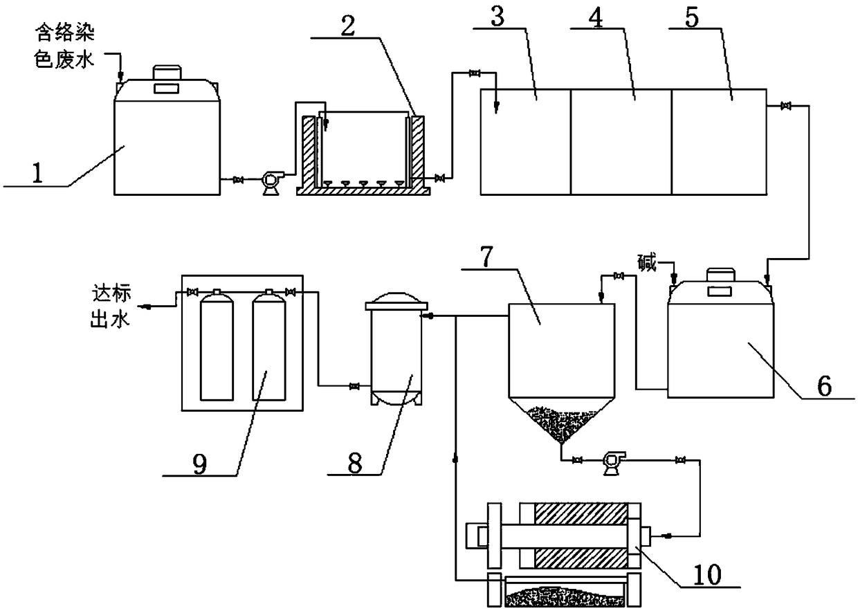
[0027] A treatment system for chromium-containing dyeing wastewater, including wastewater collection barrel 1, three-dimensional electrolysis reaction tank 2, 1#Ph adjustment tank 3, advanced oxidation decolorization tank 4, reduction tank 5, 2#Ph adjustment tank 6, 2#Ph adjustment Pool 6, filter 8, ion adsorption device 9 and mud press 10, the outlet of waste water collection bucket 1 is connected with three-dimensional electrolysis reaction tank 2, the outlet of three-dimensional electrolysis reaction tank 2 and the water inlet of 1#Ph regulating tank 3 Connection, the outlet of 1#Ph regulating tank 3 is connected with the inlet of advanced oxidation decolorization tank 4, the outlet of advanced oxidation decolorization tank 4 is connected with reduction tank 5, and the outlet of reduction tank 5 is connected with that of 2#Ph regulating tank 6. Water inlet connection, the water outlet of 2#Ph regulating pool 6 is connected with the water inlet of 2#Ph regulating pool 6, the w...

Embodiment 2

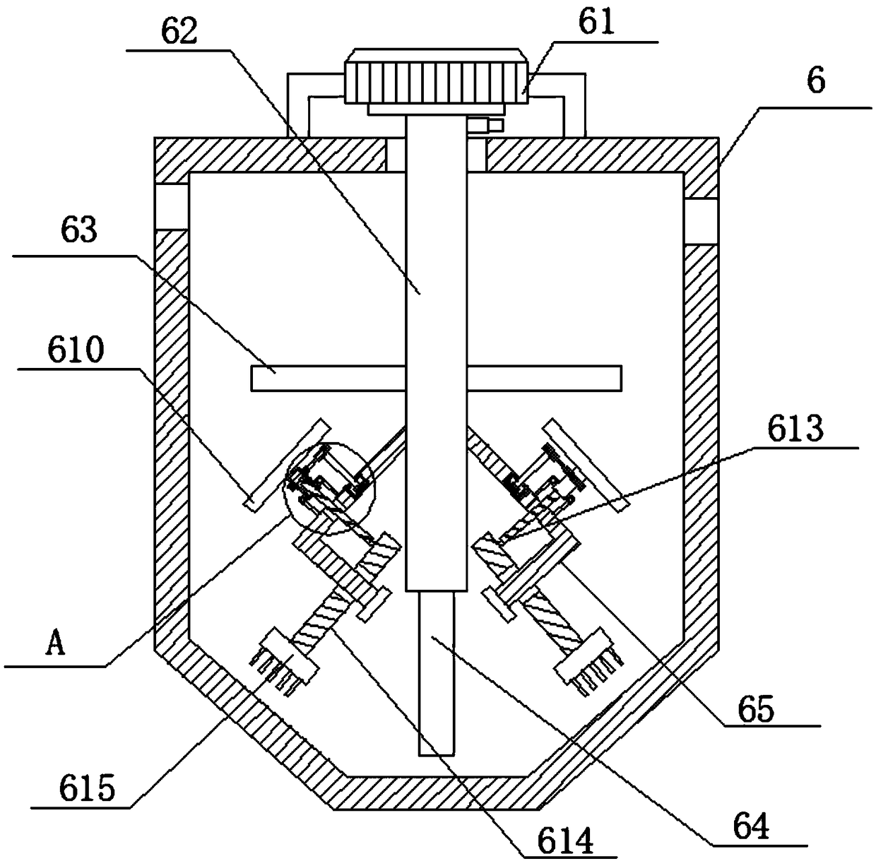
[0029] 2#Ph regulating tank 6 is equipped with a stirring device, 2#Ph regulating tank 6 is provided with a water inlet at the upper end of the side wall, 2#Ph regulating tank 6 is provided with a water outlet at the upper end of the side wall away from the water inlet, 2#Ph regulating tank The bottom end of 6 is provided with a discharge port. The stirring device includes a rotating motor 61 and a stirring shaft 62. The side wall of the rotating motor 61 is fixedly connected with the outer top wall of the 2#Ph regulating tank 6 through a support frame. The rotation on the rotating motor 61 The shaft is fixedly connected to one end of the stirring shaft 62, and the other end of the stirring shaft 62 rotates through the top of the 2#Ph regulating tank 6 to reach the inside of the 2#Ph regulating tank 6 and is fixedly connected with the vertical stirring blade 64. The stirring shaft 62 is located at 2 The side wall of a section of #Ph regulating pool 6 is symmetrically connected w...

Embodiment 3

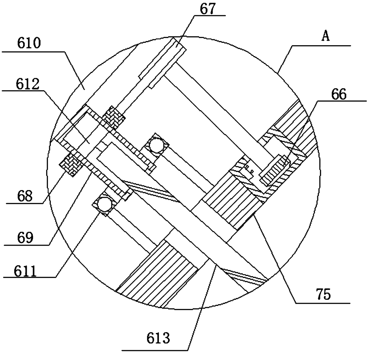
[0031] Two L-shaped connecting rods 65 are symmetrically fixedly connected with the side wall of a section of the mixing shaft 62 located in the 2#Ph regulating tank 6, and a connecting rod 614 is slidably inserted into the horizontal section of the L-shaped connecting rod 65, and one end of the connecting rod 614 is fixed One end of the treatment brush 615 is connected, the end of the L-shaped connecting rod 65 located below the connecting rod 614 is fixedly connected with a stopper, the other end of the treatment brush 615 is against the inner side wall of the 2#Ph regulating tank 6, and the other end of the connecting rod 614 One end of the threaded rod 613 is rotatably connected to the upper side, and the other end of the threaded rod 613 threaded through the vertical section of the L-shaped connecting rod 65 to reach above the L-shaped connecting rod 65 and threadedly sleeved with a sleeve 69. The threaded rod 613 is located in the sleeve. A piston 612 is rotatably connecte...


PUM


Abstract

The invention discloses a treatment system for chromium-containing dyeing wastewater and an implementation method thereof. The treatment system consists of a wastewater collection bucket, a three-dimensional electrolytic reaction tank, a 1# Ph regulating tank, an advanced oxidation decolorization tank, a reduction tank, a 2# Ph regulating tank, a flocculation sedimentation tank, a filter, an ion adsorption device and a sludge press. The treatment system for chromium-containing dyeing wastewater has a simple structure, and adopts the three-dimensional electrolysis, advanced oxidation decolorization, coagulation and ion exchange combined technology, after chromium-containing dyeing wastewater is treated by the wastewater collection bucket, the three-dimensional electrolytic reaction tank, the 1# Ph regulating tank, the advanced oxidation decolorization tank, the reduction tank, the 2# Ph regulating tank, the flocculation sedimentation tank, the filter and the ion adsorption device in order, the treated wastewater has a total chromium content of less than 0.5mg / L and a Cr<6+> content of less than 0.1mg / L that both reach the electroplating sewage discharge requirements specified in Table 3-3 of "GB 21900-2008", thus ensuring that the effluent water can achieve up-to-stand discharge and meet the reuse requirements. Also, the treatment process has strong impact load resistance.

Description

Technical field [0001] The invention relates to the technical field of electroplating dyeing wastewater, in particular to a treatment system for chromium-containing dyeing wastewater and an implementation method thereof. Background technique [0002] In metal processing, electroplating, tanning and other industries, a series of dyeing wastewater will produce a large amount of dyeing wastewater. Due to high COD, total nitrogen and total phosphorus, this type of wastewater is generally poor in biodegradability, high in color, and direct discharge will undoubtedly cause a huge environment harm. In addition, due to the widespread use of heavy metal-containing dyes, there is no doubt that this type of wastewater contains a large amount of heavy metal pollutants, of which chromium is the most toxic and the most difficult to treat. Since chromium belongs to the first type of priority control pollutant, the national environmental protection standards require separate chromium removal tr...

Claims


Application Information

Patent Timeline
Patent Type & Authority Applications(China)
IPC IPC(8): C02F9/06C02F103/16C02F101/30C02F101/22
CPCC02F9/00C02F1/56C02F1/461C02F1/66C02F1/72C02F1/725C02F1/70C02F1/001C02F1/28C02F2301/08C02F2001/46133C02F2103/16C02F2101/22C02F2101/30C02F2101/308
Inventor 吴志宇王怡旋黎建平帅和平陈福明
Owner 深圳市世清环保科技有限公司
Learn More