Flue gas purification device for improving waste heat utilization rate and denitration rate and using method thereof

A flue gas purification and utilization rate technology, which is applied in the field of flue gas purification treatment, can solve the problems of glass steel material life impact, high water content, heavy water content, etc., and achieve the effect of improving waste heat utilization rate and denitrification rate

Active Publication Date: 2018-12-07
ZHONGYE-CHANGTIAN INT ENG CO LTD
View PDF7 Cites 10 Cited by
  • Summary
  • Abstract
  • Description
  • Claims
  • Application Information

AI Technical Summary

Problems solved by technology

It can be seen that SRG gas has a large water content, high temperature, and high-temperature and high-corrosion properties. Therefore, the acid production process is made of glass fiber reinforced plastic. The glass fiber reinforced plastic material has high temperature requirements, and generally requires operation below 100 ° C. It will cause the following adverse effects: (1) In order to deal with the pollutants in SRG, a large amount of wat

Method used


Image

  • Flue gas purification device for improving waste heat utilization rate and denitration rate and using method thereof
  • Flue gas purification device for improving waste heat utilization rate and denitration rate and using method thereof
  • Flue gas purification device for improving waste heat utilization rate and denitration rate and using method thereof

Examples


Embodiment approach

[0103] According to the first embodiment provided by the present invention, a flue gas purification device for improving waste heat utilization rate and denitrification rate is provided.

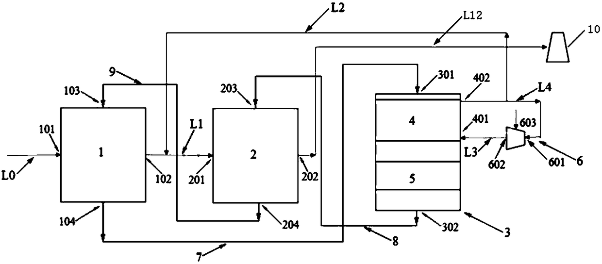
[0104] A flue gas purification device for improving waste heat utilization rate and denitrification rate, according to the direction of flue gas, the device includes a primary adsorption tower 1 and a secondary adsorption tower 2 arranged downstream of the primary adsorption tower 1 . The raw flue gas delivery pipeline L0 is connected to the flue gas inlet 101 of the primary adsorption tower 1 . The flue gas outlet 102 of the primary adsorption tower 1 is connected to the flue gas inlet 201 of the secondary adsorption tower 2 through a first pipeline L1. The device also includes a desorption tower 3 . The desorption tower 3 is provided with a heating section 4 and a cooling section 5 . The lower part of the heating section 4 is provided with a heating section gas inlet 401 , and the upper ...

Embodiment 1

[0121] Such as figure 1 As shown, a flue gas purification device for improving waste heat utilization rate and denitrification rate, according to the flue gas direction, the device includes a primary adsorption tower 1 and a secondary adsorption tower 2 arranged downstream of the primary adsorption tower 1 . The raw flue gas delivery pipeline L0 is connected to the flue gas inlet 101 of the primary adsorption tower 1 . The flue gas outlet 102 of the primary adsorption tower 1 is connected to the flue gas inlet 201 of the secondary adsorption tower 2 through a first pipeline L1. The device also includes a desorption tower 3 . The desorption tower 3 is provided with a heating section 4 and a cooling section 5 . The lower part of the heating section 4 is provided with a heating section gas inlet 401 , and the upper part of the heating section 4 is provided with a heating section gas outlet 402 . The gas outlet 402 of the heating section of the analysis tower 3 is connected to ...

Embodiment 2

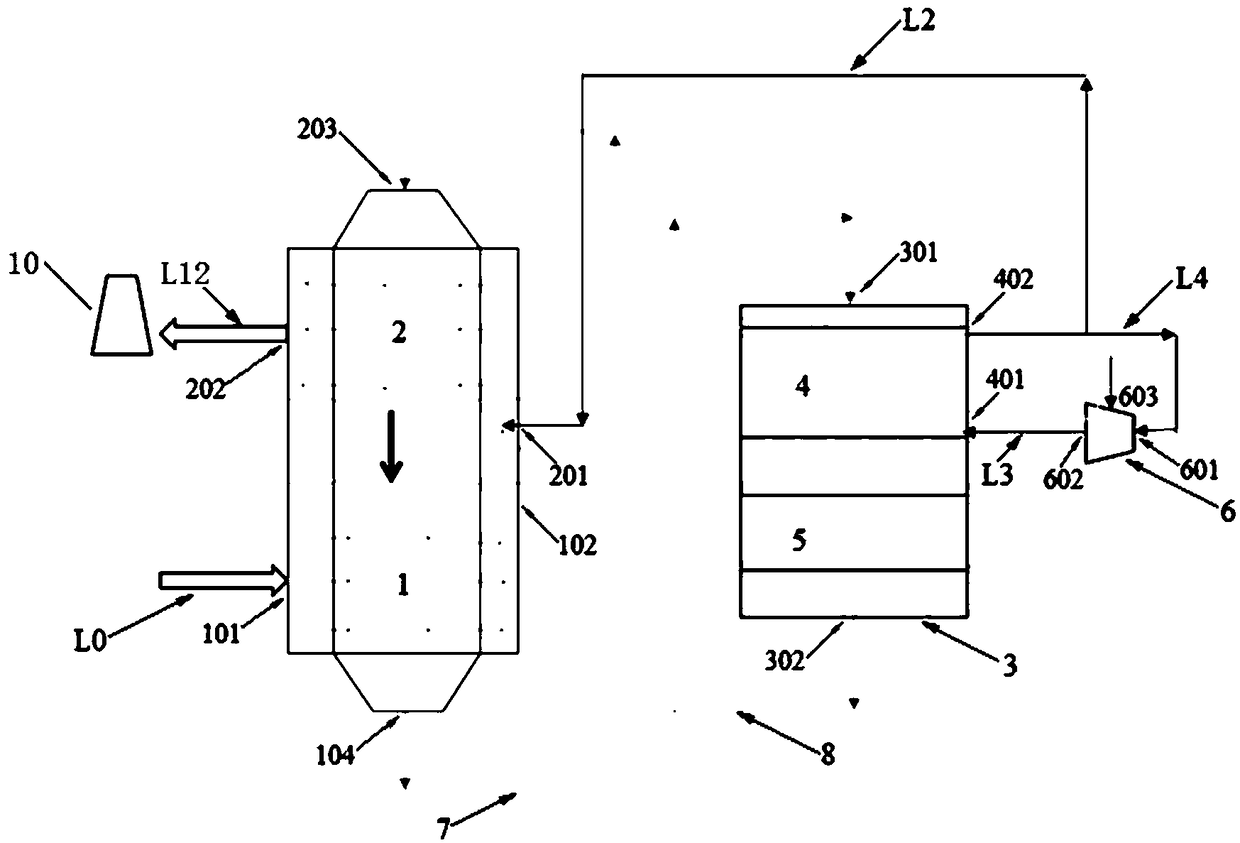
[0126] Repeat Example 1, except that the secondary adsorption tower 2 is arranged on the top of the primary adsorption tower 1. The top of the secondary adsorption tower 2 is provided with a secondary adsorption tower activated carbon inlet 203 . The bottom of the primary adsorption tower 1 is provided with an outlet 104 for the activated carbon of the primary adsorption tower. The top of the analysis tower 3 is provided with an inlet 301 for the activated carbon of the analysis tower. The bottom of the analysis tower 3 is provided with an outlet 302 for the activated carbon of the analysis tower.

[0127] Wherein, the activated carbon outlet 104 of the primary adsorption tower is connected with the activated carbon inlet 301 of the desorption tower. The activated carbon outlet 302 of the analysis tower is connected with the activated carbon inlet 203 of the secondary adsorption tower.

[0128] The device also includes a first conveyor 7 for transporting the activated carbo...


PUM


Abstract

According to a trend of flue gas, the flue gas purification device for improving waste heat utilization rate and denitration rate includes a primary adsorption column and a secondary adsorption columndisposed downstream the primary adsorption column. An original flue gas conveying pipeline is connected to a flue gas inlet of the primary adsorption column; a flue gas outlet of the primary adsorption column is connected to a flue gas inlet of the secondary adsorption column through a first pipeline; the device further comprises an analytical tower; a heating section and a cooling section are disposed on the analytical tower; the lower part of the heating section is provided with a heating section gas inlet, and the upper part of the heating section is provided with a heating section gas outlet; and the heating section gas outlet of the analytical tower is connected to the flue gas inlet of the secondary adsorption column by a second pipeline. The device introduces a part of exhausted hot air after heat exchange with to-be-analyzed activated carbon into the flue gas inlet of the secondary adsorption column, and on one hand, the concentration of exhausted SO<2> is removed, and simultaneously flue gas at the inlet of the secondary adsorption column is heated to improve the temperature of the flue gas.

Description

technical field [0001] The invention relates to an activated carbon flue gas purification device and the purification thereof, in particular to a flue gas purification device for improving waste heat utilization rate and denitrification rate, and belongs to the field of flue gas purification treatment. Background technique [0002] The discharge temperature of sintering flue gas is between 110-170°C, which contains SO 2 , NO x , dust, dioxins, heavy metals and other pollutants, and the activated carbon flue gas purification technology is just suitable for the sintering flue gas temperature emission range, which can realize the synergistic and efficient purification of multiple pollutants, and can simultaneously remove a variety of pollutants on a set of equipment Pollutants, achieving by-product SO 2 The utilization of resources, and this technology has the advantages of high pollutant removal efficiency, basically no consumption of water resources, and no secondary pollut...

Claims


Application Information

Patent Timeline
IPC IPC(8): B01D53/02B01D53/06F27D17/00
CPCB01D53/02B01D53/06B01D2257/302B01D2257/40B01D2258/0283B01D2259/40022B01D2259/40088B01D2259/4009F27D17/008
Inventor 李俊杰魏进超李小龙
Owner ZHONGYE-CHANGTIAN INT ENG CO LTD
Why Eureka
Try Eureka