Method for recovering nitrogen, phosphorus and fluorine based on electrochemical reactor

A recovery method and reactor technology, applied in the direction of electrolysis components, electrolysis process, etc., can solve the problems of complex nitrogen, phosphorus and fluorine recovery process, and achieve the effects of shortening the settling time, small footprint of the device, and improving the removal rate.

Active Publication Date: 2018-12-11
HUBEI MEICHEN ENVIRONMENTAL PROTECTION CO LTD +1
View PDF6 Cites 6 Cited by
  • Summary
  • Abstract
  • Description
  • Claims
  • Application Information

AI Technical Summary

Problems solved by technology

[0004] The invention solves the technical problems in the prior art that the recovery process of nitrogen, phosphorus and fluoride is complex, requires regular dosing of medicaments, and requires multiple pH adjustments

Method used


Image

  • Method for recovering nitrogen, phosphorus and fluorine based on electrochemical reactor
  • Method for recovering nitrogen, phosphorus and fluorine based on electrochemical reactor

Examples


Embodiment 1

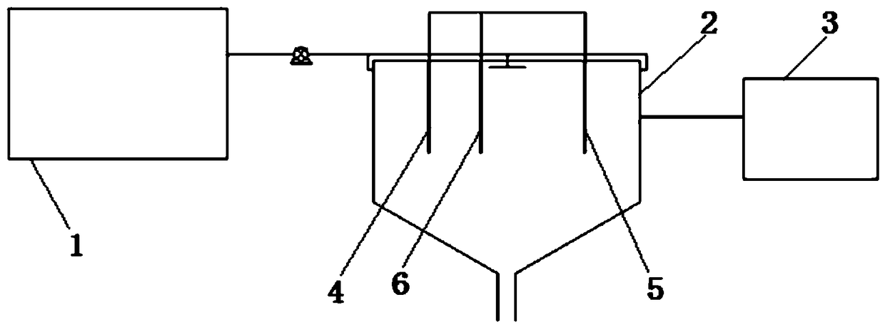
[0023] The present invention is a method for recovering nitrogen, phosphorus and fluorine based on an electrochemical reactor, which uses figure 1 The device shown includes a grit chamber 1; an electrochemical reaction tank 2; a water storage tank 3; a calcium-magnesium alloy rod 4; a graphite rod 5 and a stainless steel plate 6. In this method, firstly, the waste water from the slag field flows into the grit chamber 1, and is precipitated and separated to remove larger massive impurities and floating objects in the waste water, and then the waste water flows through the electrochemical reaction tank 2, and calcium is put into the electrochemical reaction tank respectively. Magnesium alloy rod 4, graphite rod 5, and stainless steel plate 6. Under the action of direct current, the electrochemical reaction cell is divided into three steps, followed by the first two steps to put the calcium-magnesium alloy rod 4 and the graphite rod 5, and the third step to put the graphite rod 5...

Embodiment 2

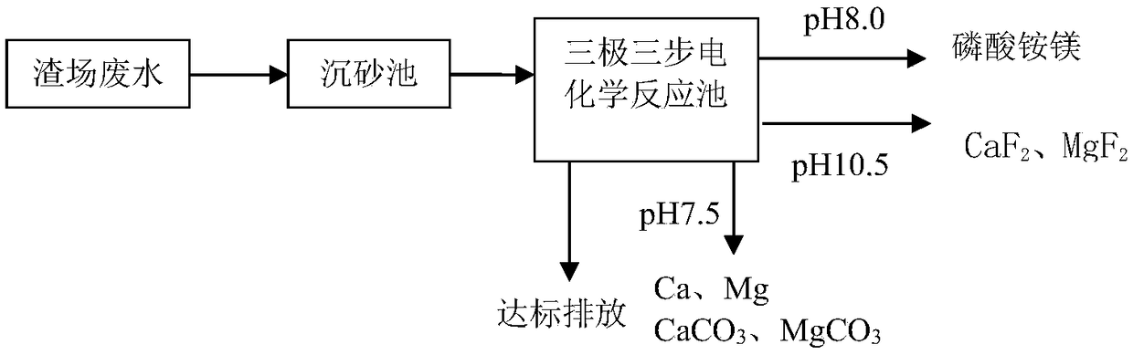
[0045] The seepage discharge of a phosphogypsum slag field is 1200m 3 / d, wherein the phosphorus content in the wastewater is 2500mg / L, the fluorine content is 1200mg / L, the ammonia nitrogen content is 400mg / L, and the pH is 4. Wastewater from the slag field flows into the grit chamber 1, and is precipitated and separated to remove larger massive impurities and floating objects in the waste water, and is lifted into the electrochemical reaction tank 2 by a lift pump. Under the action of direct current, calcium-magnesium alloy rods 4, graphite rods 5 and stainless steel plates 6 are sequentially put into the electrochemical reaction cell. In the first step, the calcium-magnesium alloy rod 4 is placed as the anode, and the graphite rod 5 is used as the cathode, and electron transfer occurs to provide Mg 2+ and OH - , pH gradually increased to 8.5, Mg 2+ Phosphorus, nitrogen and other substances in the waste water are precipitated and removed in the form of fertilizers such as...


PUM


Abstract

The invention relates to a method for recovering nitrogen, phosphorus and fluorine based on an electrochemical reactor, which belongs to the technical field of hazardous waste treatment. In the firststep of the method, a calcium-magnesium alloy rod is used as an anode to provide Mg<2+> and Ca<2+> by the loss of electrons, a graphite rod is used as a cathode to precipitate OH<->, and the Mg<2+> reacts with NH4<+> and PO4<3-> in a supernatant to form a magnesium ammonium phosphate sediment; in the second step, the Mg<2+> and Ca<2+> react with F<-> in the solution respectively to form a sediment; in the third step, a graphite rod is used as an anode, and a stainless steel plate is used as a cathode; the anode loses electrons, precipitates H<+> and CO3<2->, one part of Mg<2+> and Ca<2+> in the supernatant get electrons to be reduced to elemental calcium and elemental magnesium, and the other part of Mg<2+> and Ca<2+> react with the CO3<2-> respectively to form MgCO3 and CaCO3 sediment; the remaining NH4<+> in the supernatant is air stripped to react with OH<-> to form NH3; and the NO3<-> in the supernatant gets electrons to form N2. The method does not need to add a chemical, or adjust a pH, and only needs to exist in one reaction pool, the aim of recycling of the nitrogen, phosphorus and fluorine in dreg site waste water can be realized.

Description

technical field [0001] The invention relates to the technical field of hazardous waste treatment, in particular to a nitrogen, phosphorus and fluorine recovery method based on an electrochemical reactor. Background technique [0002] With the rapid development of industrialization, the impact of wastewater from phosphogypsum slag yards and phosphorus chemical production systems on the environment has become increasingly prominent. Studies have shown that phosphorus chemical wastewater has strong acidity and strong corrosiveness; the content of total phosphorus and fluoride is high, and the content of ammonia nitrogen is high, and its treatment is difficult. If nitrogen and phosphorus are excessive, it is easy to cause eutrophication of water body. [0003] Because the traditional nitrogen and phosphorus recovery process mainly adopts physical and chemical methods, the process flow is complex, the device occupies a large area, and the time is too long; at the same time, it n...

Claims


Application Information

Patent Timeline
Patent Type & Authority Applications(China)
IPC IPC(8): C25B1/00C25B1/24
CPCC25B1/00C25B1/245
Inventor 吴旭付饶王芳祝国亮周正吕航张艳琳吴丹丹古月圆
Owner HUBEI MEICHEN ENVIRONMENTAL PROTECTION CO LTD
Why Eureka
Try Eureka