System and method for high-temperature biomass gas cooling and waste heat utilization

A biomass gas, high temperature technology, applied in combustion methods, reduction of greenhouse gases, treatment of combustion products, etc., can solve the problems of long flue length, increased cost, and many elbows, etc., and achieves high purity and added value. High, avoid tar deposition effect

Active Publication Date: 2018-12-21
SHANDONG ELECTRIC POWER ENG CONSULTING INST CORP
View PDF5 Cites 5 Cited by
  • Summary
  • Abstract
  • Description
  • Claims
  • Application Information

AI Technical Summary

Problems solved by technology

However, the air preheater is generally located at a height of more than 20 meters. If the high-temperature flue gas is drawn from the front of the air preheater to zero meters, the flue length will be longer and there will be more elbows. After passing through the dust collector, it is easy to cause dust accumulation at the elbow; if the high-temperature flue gas is drawn from the front of the air preheater to the independent evaporation tower built on the boiler steel frame in order to reduce the length of the flue, it will cause new damage to the boiler steel frame. Adding a large load, especially for the renovation project, generally requires reinforcement to increase the large load on the original boiler steel frame, and the reinforcement generally requires a large increase in cost

Method used


Image

  • System and method for high-temperature biomass gas cooling and waste heat utilization
  • System and method for high-temperature biomass gas cooling and waste heat utilization
  • System and method for high-temperature biomass gas cooling and waste heat utilization

Examples


Embodiment 1

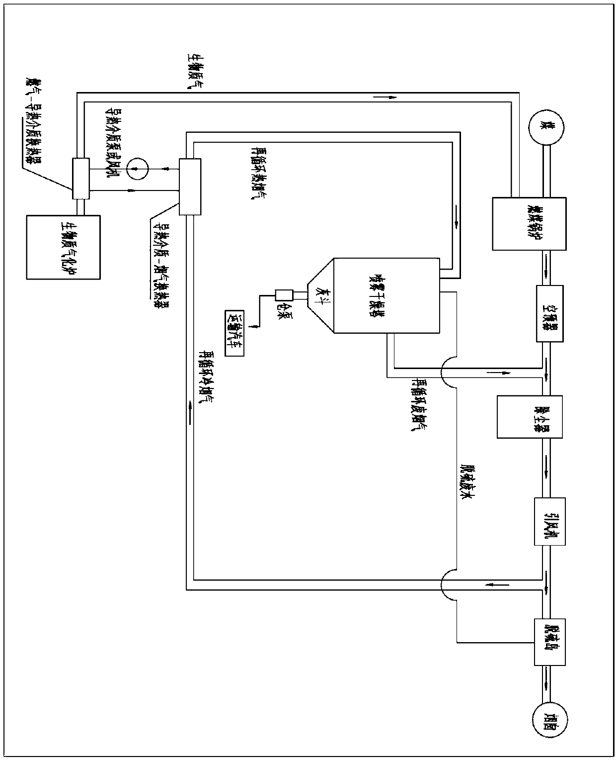
[0044] In one or more embodiments, a system for cooling high-temperature biomass gas and utilizing waste heat is disclosed, such as figure 1 As shown, it includes: the coal-fired boiler is connected in series with the air preheater, the dust collector, the induced draft fan and the desulfurization island to form the main flue; the desulfurization wastewater generated by the desulfurization island enters the spray drying tower through the pipeline. The flue gas recirculation flue is drawn out from the flue after the induced draft fan and before the desulfurization island. The flue gas recirculation flue is connected with the heat transfer medium-flue gas heat exchanger, and the flue gas enters the heat transfer medium-flue gas heat exchanger for heat exchange. , the flue gas after heat exchange is discharged from the heat transfer medium-flue gas heat exchanger into the spray drying tower to realize the evaporation and crystallization of desulfurization wastewater. Most of the p...

Embodiment 2

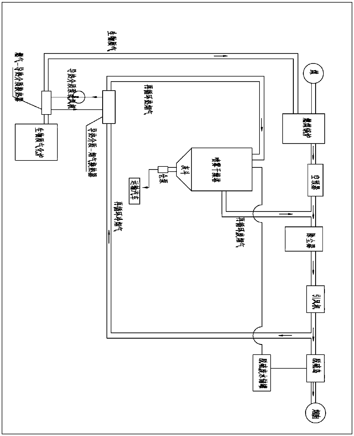
[0050] In other embodiments, a high-temperature biomass gas cooling and waste heat utilization system is disclosed, such as figure 2 As shown, a desulfurization wastewater storage tank is set between the desulfurization island and the spray drying tower, the desulfurization wastewater outlet of the desulfurization island is connected to the inlet of the desulfurization wastewater storage tank, and the outlet of the desulfurization wastewater storage tank is connected to the inlet of the spray drying tower. When the biomass gasifier is out of operation for a short period of time, the desulfurization wastewater generated by the coal-fired unit is temporarily stored in the desulfurization wastewater storage tank due to the shutdown of the biomass gas. When the biomass gasifier is put into operation, Then spray the desulfurization wastewater in the desulfurization wastewater storage tank into the spray drying tower.

[0051] It should be noted that the definition of the length of...

Embodiment 3

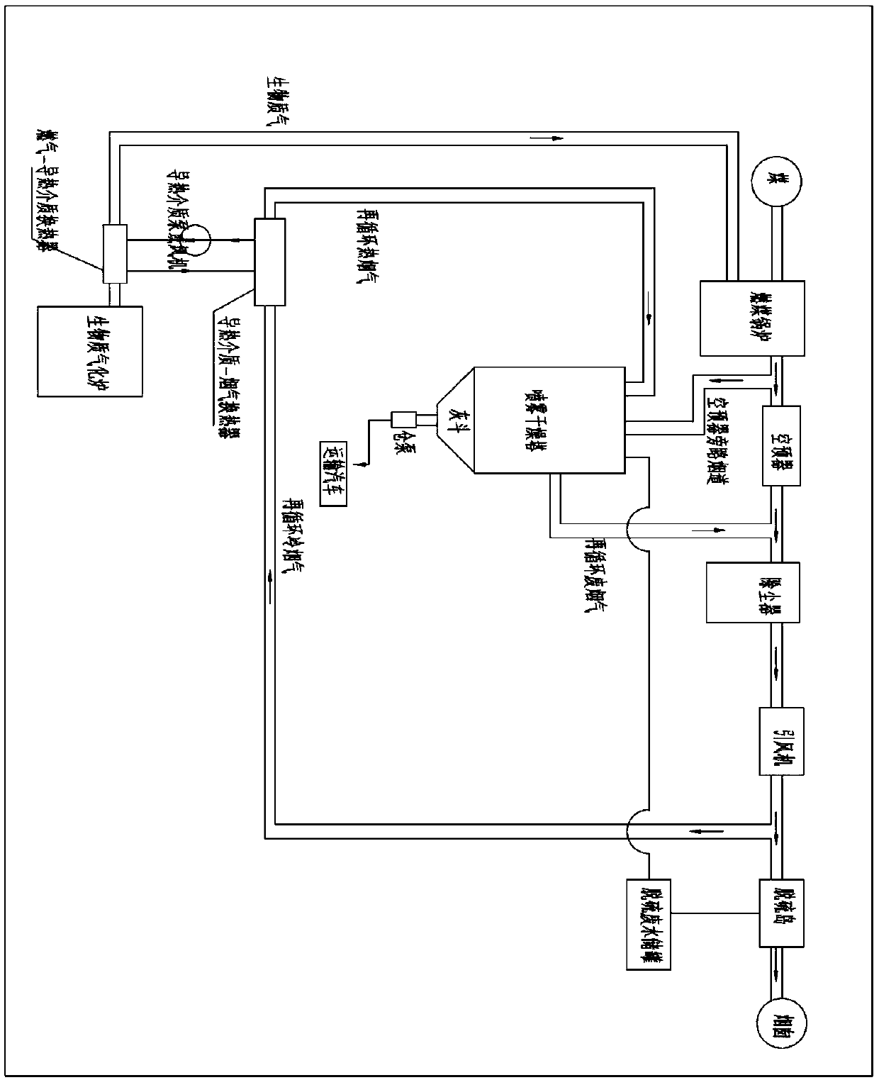
[0054] In other embodiments, a high-temperature biomass gas cooling and waste heat utilization system is disclosed, such as image 3 As shown, a desulfurization wastewater storage tank is set between the desulfurization island and the spray drying tower, the desulfurization wastewater outlet of the desulfurization island is connected to the inlet of the desulfurization wastewater storage tank, and the outlet of the desulfurization wastewater storage tank is connected to the inlet of the spray drying tower. When the biomass gasifier is out of operation for a short period of time, the desulfurization wastewater generated by the coal-fired unit is temporarily stored in the desulfurization wastewater storage tank due to the shutdown of the biomass gas. When the biomass gasifier is put into operation, Then spray the desulfurization wastewater in the desulfurization wastewater storage tank into the spray drying tower.

[0055] In addition, an air preheater bypass flue connected to t...


PUM


Abstract

The invention discloses a system and method for high-temperature biomass gas cooling and waste heat utilization. A main flue formed by a coal-fired boiler, an air preheater, a dust collector, an induced draft fan and a desulfurization island which are connected in series is included, and a flue gas recirculation pipe, a heat conducting medium-flue gas heat exchanger, a gas-heat conducting medium heat exchanger and a spray drying tower are further included; the spray drying tower is connected to the part, in front of the dust collector, of the main flue, the flue gas recirculation pipe is connected to the part, behind the dust collector, of the main flue, and the main flue communicates with the heat conducting medium-flue gas heat exchanger through the flue gas recirculation pipe; and fluegas of the heat conducting medium-flue gas heat exchanger communicates with the spray drying tower, a heat conducting medium of the heat conducting medium-flue gas heat exchanger is in communication with the gas-heat conducting medium heat exchanger, and gas of the gas-heat conducting medium heat exchanger communicates with the coal-fired boiler. By means of the system and method, sensible heat ofwaste biomass gas is utilized to remove harmful substances in desulfurization waste water, energy saving and environment protection can be achieved, and by-product salt crystals are high in purity and high in added value.

Description

technical field [0001] The invention belongs to the field of coal-fired coupled biomass power generation, and in particular relates to a system and method for cooling high-temperature biomass gas and utilizing waste heat. Background technique [0002] Coal-fired coupled biomass coupled power generation technology can solve social governance problems such as direct burning of straw in the field, overcome the shortcomings of high pollutant emission levels in the energy utilization of biomass resources, and promote the low-carbon and clean development of the power industry, especially coal power. Among them, the coupling of biomass gasification is an important way of coupled power generation. [0003] Biomass circulating fluidized bed gasification is through biomass oxidative combustion, reduction and thermal decomposition reactions in the gasifier, including the combustion of some raw materials with oxygen in the air to provide the energy required for reduction and thermal dec...

Claims


Application Information

Patent Timeline
Patent Type & Authority Applications(China)
IPC IPC(8): F23J15/06F23J15/02F26B21/00
CPCF23J15/025F23J15/06F23J2215/20F23J2217/10F26B21/002Y02E20/30
Inventor 祁金胜刘义达李官鹏苗井泉徐广强王毅苏乐
Owner SHANDONG ELECTRIC POWER ENG CONSULTING INST CORP
Why Eureka
Try Eureka