Novel fluidized bed smoke furnace

A flue gas furnace and fluidized bed technology, which is applied in the field of new fluidized bed flue gas furnace, can solve the problems of shortened furnace wall maintenance cycle, failure to feed materials normally, and reduced furnace life, so as to improve fuel adaptability and combustion Strength, reduce labor intensity, reduce the effect of the probability of pipe blockage

Pending Publication Date: 2019-02-15
HUBEI JINLU ENERGY SAVING LTD CO
View PDF0 Cites 1 Cited by
  • Summary
  • Abstract
  • Description
  • Claims
  • Application Information

AI Technical Summary

Problems solved by technology

[0004] 1. It is difficult to enlarge the furnace body. The original fluidized bed furnace type is mostly less than 14MW furnace type. The traditional straight wall structure can meet the requirements of use. In the process of large-scale furnace body, due to the increase in the height of the furnace wall, the furnace wall The expansion of the furnace is increased, and the height is increased without increasing the thickness of the furnace wall, the life of the furnace body is greatly reduced, and the maintenance cycle of the furnace wall is shortened
[0005] 2. The fuel adaptability is poor. There are various types of pellet fuel. According to the volatile content from low to high, the ignition temperature of the fuel burns from high to low. The traditional furnace type does not have a lot of fuel adaptability. Good adjustability, high requirements for the operator's experience as a fireman, low fault tolerance and tolerance in the combustion process
[0006] 3. The combustion intensity of the furnace is low. During the combustion process of the traditional furnace type, the volume space of the furnace is insufficiently utilized. When the fluidized bed furnace is working, the furnace can be divided into a dense phase area at the lower end and a dilute phase area at the upper end. The dense phase area of ​​the traditional furnace type The phase zone is short, and the local high-temperature zone cannot be adjusted, resulting in coke hanging on the furnace wall. Lengthening the dense phase zone is beneficial to improve the combustion intensity, but the traditional furnace type has the problem of difficult feeding in the dense phase zone: the current feeding method in the dense phase zone is A screw conveyor passing through the furnace wall is installed in the dense phase area of ​​the furnace, accompanied by cooling air, and the material is

Method used


Image

  • Novel fluidized bed smoke furnace
  • Novel fluidized bed smoke furnace
  • Novel fluidized bed smoke furnace

Examples


Embodiment 1

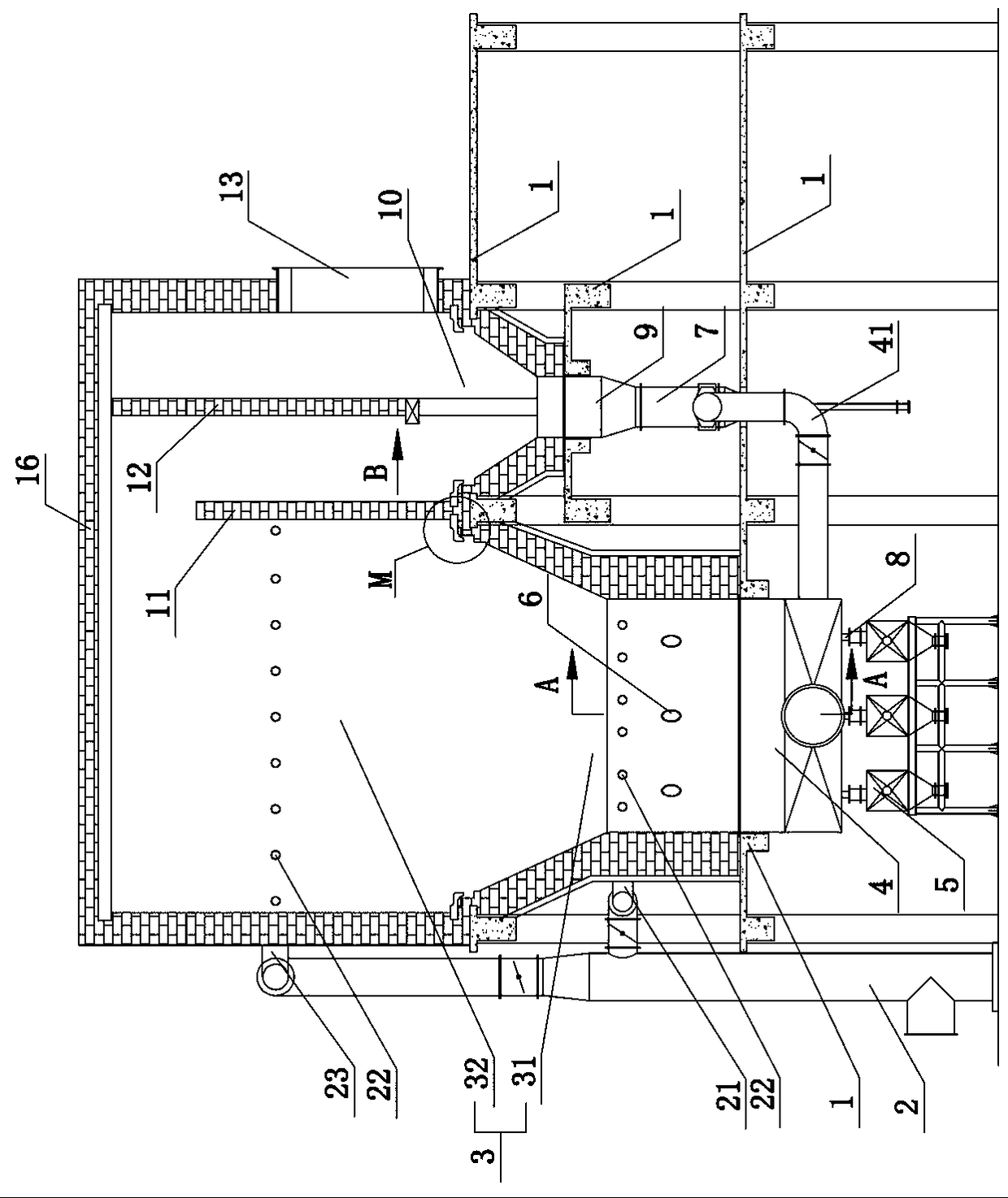
[0051] see Figure 1-3 , the present embodiment includes a support platform 1, a furnace body is installed on the support platform 1, a main furnace chamber 3 and an auxiliary furnace chamber 10 are arranged in the furnace body, a fire retaining wall 11 is provided between the main furnace chamber 3 and the auxiliary furnace chamber 10, and the auxiliary furnace chamber 10 is equipped with a collection The dust wall 12, the auxiliary furnace 10 is provided with a flue gas outlet 13, the main furnace 3 is equipped with a bellows 4 for supplying air to the main furnace 3, and the bellows 4 is equipped with a secondary combustion air pipe 41 for supplying air to the auxiliary furnace 10, the support The platform 1 is divided into two parts, one part supports the dilute phase region 32 of the main furnace 3 and the auxiliary furnace 10, and the other part supports the dense phase region 31 of the main furnace 3 and the auxiliary furnace 10; the furnace wall 614 of the main furnace ...

Embodiment 2

[0075] see Figure 16 , the structure of this embodiment is basically the same as that of the first embodiment, the difference is that the fire retaining wall 11 includes a lining refractory brick layer 113, a thermal insulation material layer 114, a peripheral clay brick layer 115, and the lining refractory brick layer 113 and the peripheral clay brick layer 115. A layer of connecting bricks is built at a certain height between the brick layers 115, and the connecting bricks are button-type connecting bricks 116. The two-layer button-type connecting bricks 116 are arranged in a staggered horizontal interlocking arrangement, that is, two adjacent buttons The type connecting bricks 116 are pulled and connected in the horizontal direction, and can be shifted in the vertical direction, and most of one of the buckle type connection bricks 116 is placed in the lining refractory brick layer 113, and the large part of the other buckle type connection brick 116. Part of it is placed i...


PUM


Abstract

The invention discloses a novel fluidized bed smoke furnace. The novel fluidized bed smoke furnace comprises a supporting platform. The supporting platform is provided with a furnace body. The furnacebody is internally provided with a main hearth and an auxiliary hearth. A fire barrier is arranged between the main hearth and the auxiliary hearth. The auxiliary hearth is internally provided with adust collection wall, and the auxiliary hearth is provided with a smoke outlet. An air bellow for supplying air to the main hearth is arranged below the main hearth, and the air bellow is provided with an auxiliary combustion air pipe for supplying air to the auxiliary hearth. The supporting platform is divided into two parts, one part is used for supporting lean-phase zones of the main hearth and the auxiliary hearth, and the other part is used for supporting dense-phase zones of the main hearth and the auxiliary hearth. A furnace wall of the main hearth is provided with a plurality of setsof gravity type positive pressure high-temperature feeders. Each gravity type positive pressure high-temperature feeder comprises a feeding pipe extending into the hearths, wherein the inner end of the feeding pipe extends into positive pressure zones in the hearths. One end of the air bellow is provided with a main air pipe, the main air pipe is provided with a nozzle extending into the hearths and an air guiding pipe connected with the outer ends of the feeding pipes. By means of the novel fluidized bed smoke furnace, the fuel adaptation and the combustion intensity are improved, and meanwhile the service life of a furnace body is not affected.

Description

technical field [0001] The invention relates to the technical field of fluidized bed flue gas furnaces, in particular to a novel fluidized bed flue gas furnace. Background technique [0002] The fluidized bed flue gas furnace is a type of furnace used for burning granular fuel. The traditional fluidized bed flue gas furnace is also called a boiling furnace. It consists of a furnace body and a fluidized air distribution device. The granular fuel passes through the fuel feeding port by gravity. It is sent to the hearth of the fluidized furnace, and the combustion-supporting air is sent into the hearth by the bellows, and the fuel is suspended and burned on the hearth through the fluidized air distribution plate. live. [0003] With the progress of industrialization, the requirements for industrial equipment are gradually increasing. The traditional fluidized bed furnace type has the following problems: [0004] 1. It is difficult to enlarge the furnace body. The original flu...

Claims


Application Information

Patent Timeline
IPC IPC(8): F23C10/00F23C10/18
CPCF23C10/00F23C10/18
Inventor 杨年龙蔡伦
Owner HUBEI JINLU ENERGY SAVING LTD CO
Why Eureka
Try Eureka