Preparation method of large core diameter optical fiber preform rod and optical fiber

An optical fiber preform, large core diameter technology, applied in glass manufacturing equipment, manufacturing tools, etc., can solve the problems of uneven distribution of the core refractive index, large background loss of the optical fiber, small core diameter, etc., and achieve uniform refractive index distribution, Simple preparation process

Active Publication Date: 2020-09-01
XI'AN INST OF OPTICS & FINE MECHANICS - CHINESE ACAD OF SCI
View PDF6 Cites 0 Cited by
  • Summary
  • Abstract
  • Description
  • Claims
  • Application Information

AI Technical Summary

Problems solved by technology

[0005] Aiming at the technical problems that the optical fiber preform prepared by the existing method has a small core diameter, uneven distribution of the core refractive index in the optical fiber preform, and large background loss of the optical fiber, the present invention provides a method for preparing an optical fiber preform with a large core diameter The method and the method for preparing an optical fiber using the large-core-diameter optical fiber preform prepared by the method, the core diameter of the prepared preform is > 3 mm, which greatly improves the optical fiber yield of a single preform, and the prepared optical fiber preform The axial refractive index and radial refractive index of the core are relatively uniform, and the numerical aperture is 0.06±0.005

Method used


Image

  • Preparation method of large core diameter optical fiber preform rod and optical fiber
  • Preparation method of large core diameter optical fiber preform rod and optical fiber
  • Preparation method of large core diameter optical fiber preform rod and optical fiber

Examples


Embodiment 1

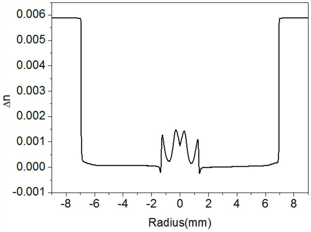
[0059] Calculate the gaseous reaction material Al(acac) according to the formula composition requirements of the large core diameter optical fiber preform core 3 , POCl 3 、SiCl 4 、Yb(thd) 3 and SiF 4 and set the flow rate of the gaseous reaction material in the MCVD automatic control software, as shown in Table 1; connect the quartz tube to the MCVD deposition lathe, preheat the quartz tube with a hydrogen-oxygen flame, and pass it into SF after the preheating is completed. 6 The gas erodes the inner wall of the quartz tube. After the erosion, the gas material is passed into the quartz tube according to the set flow value to start depositing the core layer; during the deposition process, the heating temperature of the quartz tube is 1850 ° C, and the rotation speed of the tube is 30 rpm. The moving speed of the oxyhydrogen flame is 100mm / min; after the deposition is finished, the Cl 2 Shrunk quartz tube, Cl 2 The flow rate is 5mL / min. After the hollow tube has been shrunk...

Embodiment 2

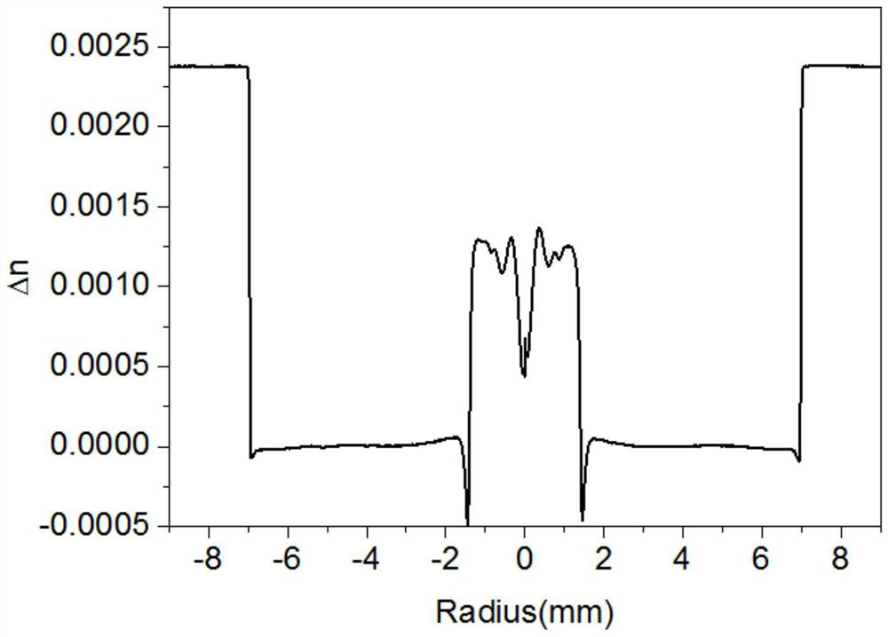
[0064] According to the component flow rate of the optical fiber preform in embodiment one and the refractive index profile of the preform, adjust the component Al(acac) 3 , POCl 3 、Yb(thd) 3 or SiF 4 The flow rate is set in the MCVD automatic control software. The set values ​​are shown in Table 2; SF 6 The gas erodes the inner wall of the quartz tube; after the erosion, the gas material is passed into the quartz tube according to the set flow value to start depositing the core layer; during the deposition process, the heating temperature of the quartz tube is 1850 ° C, and the rotation speed of the tube is 30 rpm minutes, the moving speed during the oxyhydrogen flame deposition process is 100mm / min; 2 Shrunk quartz tube, Cl 2 The flow rate is 5mL / min. After the hollow tube has been shrunk several times and fired into a solid rod, the optical fiber preform is flame-polished at 1600°C. The prepared large-core optical fiber preform was fused at high temperature, and its r...

Embodiment 3

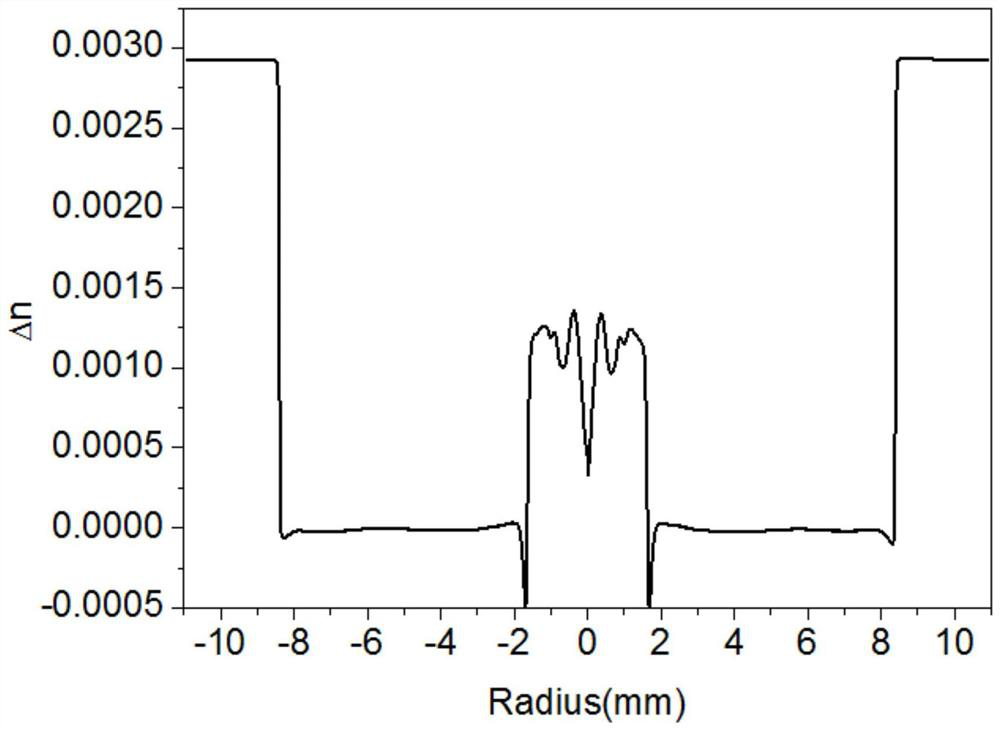
[0069] According to the formula component requirements of the large-diameter optical fiber preform core, combined with the component flow rate and refractive index distribution results of the optical fiber preform in Example 1, each of the deposition layers set in the MCVD automatic control software in this embodiment The flow values ​​of the components are shown in Table 3; after the setting is completed, the quartz tube is connected to the MCVD deposition lathe, and the quartz tube is preheated by the hydrogen-oxygen flame. After the preheating is completed, the SF 6 The gas erodes the inner wall of the quartz tube; after the erosion, the gas material is passed into the quartz tube according to the set flow value to start depositing the core layer; during the deposition process, the heating temperature of the quartz tube is 1900 ° C, and the rotation speed of the tube is 30 rpm Minutes, the moving speed of the oxyhydrogen flame is 100mm / min; after the deposition is completed,...


PUM

PropertyMeasurementUnit
sizeaaaaaaaaaa
diameteraaaaaaaaaa

Abstract

The invention relates to methods for preparing optical fiber preforms and optical fibers, in particular to methods for preparing optical fiber preforms with large core diameters and corresponding low-loss optical fibers. By the aid of the methods, the problem of small core diameters of optical fiber preforms prepared in the prior art can be solved. The method for preparing the optical fiber preforms with the large core diameters includes depositing all materials under vapor-phase conditions by the aid of modified chemical vapor deposition (MCVD) and rare earth ion vapor-phase doping processes;carrying out sintering and tube shrinking technologies to obtain the optical fiber preforms with the large core diameters. The prepared optical fiber preforms comprise SiO2, Al2O3, P2O5, Yb2O3 and F,and the diameters of cores of the prepared optical fiber preforms are larger than 3 mm. The method for preparing the optical fibers includes sleeving the prepared optical fiber preforms with the large core diameters by the aid of selected appropriate sleeving technologies to allow the requirements of the optical fibers to be met by the core-cladding ratios of the optical fiber preforms; processing sleeved preforms to allow the preforms to obtain octagonal structures; drawing wires at the temperatures of 2050+ / -20 DEG C to obtain the optical fibers by means of drawing.

Description

technical field [0001] The invention relates to a method for preparing an optical fiber preform and an optical fiber, in particular to a method for preparing a large core-diameter optical fiber preform and a corresponding low-loss optical fiber. Background technique [0002] Fiber lasers are called the third-generation lasers. Compared with traditional lasers, fiber lasers have many advantages, such as high electro-optical conversion efficiency, good beam quality, long service life, strong environmental adaptability, and small footprint. They are energy-saving and environmentally friendly. Optoelectronic devices have been widely used in industrial manufacturing, medical treatment, energy exploration, military defense and other fields, and the growth rate of their market sales has reached double digits for several consecutive years. [0003] As the core device of high-power fiber lasers, laser fiber materials are the key factors that determine the power of fiber lasers, and e...

Claims


Application Information

Patent Timeline
Patent Type & Authority Patents(China)
IPC IPC(8): C03B37/018C03B37/027
CPCC03B37/01807C03B37/01815C03B37/027
Inventor 侯超奇折胜飞李玮楠常畅赵保银郑锦坤李哲高菘张岩
Owner XI'AN INST OF OPTICS & FINE MECHANICS - CHINESE ACAD OF SCI
Why Eureka
Try Eureka