A kind of all-crystal fiber and cladding manufacturing process

A crystal optical fiber and manufacturing process technology, applied in the field of crystal material preparation, can solve the problems of easy cracking of the cladding, low process pass rate, low sol-gel efficiency, etc., and achieve the effect of uniform refractive index distribution and high power

Active Publication Date: 2020-03-24
TONGJI UNIV
View PDF5 Cites 0 Cited by
  • Summary
  • Abstract
  • Description
  • Claims
  • Application Information

AI Technical Summary

Problems solved by technology

[0003] However, almost all optical fibers need cladding, not only to confine the beam inside the fiber, but also to isolate the fiber from the surrounding environment to maintain the integrity of the fiber. The cladding can also be used to increase the strength of the fiber. For Silica optical fiber, the cladding of the optical fiber is made by putting the quartz tube and the quartz core together to make a prefabricated rod, which is co-drawn in the fiber drawing tower, because the quartz is heated to soften and has a state between solid and liquid. The softened state exists, the dopant that has been doped into the core will not diffuse, and the refractive index distribution in the original preform will be maintained. For the crystal fiber, since the crystal is in a liquid state after melting, it can diffuse freely, so the dopant in the core rod It is possible for the ions to diffuse into the tube rod, and the tube rod as the fiber cladding does not allow the presence of doping ions, so it is not advisable to make the crystal cladding by the method of making the quartz cladding
Units at home and abroad are trying sol-gel to make crystal optical fiber cladding, but no substantial progress has been made, because the efficiency of sol-gel is too low, and the cladding with a thickness of 5 μm can only be obtained after 10 sol-gel operations, which is far from the final The usable thickness of 200-300μm is far away, and the cladding made by sol-gel is easy to crack
At present, there is no mature process report on crystal fiber with crystal cladding at home and abroad. It is reported that the crystal core and quartz cladding are used. Good beam quality, but it does not have much effect on the amplification of laser power. The US ArmyResearch Laboratory and ONYX Optics turned to study planar guided waves---that is, the cross-section of the core rod and cladding was made square, and the core and cladding They are tightly bonded by thermal bonding, and the all-crystal fiber is truly achieved, but the qualification rate of this thermal bonding process is not high.

Method used


Image

  • A kind of all-crystal fiber and cladding manufacturing process
  • A kind of all-crystal fiber and cladding manufacturing process
  • A kind of all-crystal fiber and cladding manufacturing process

Examples


Embodiment 1

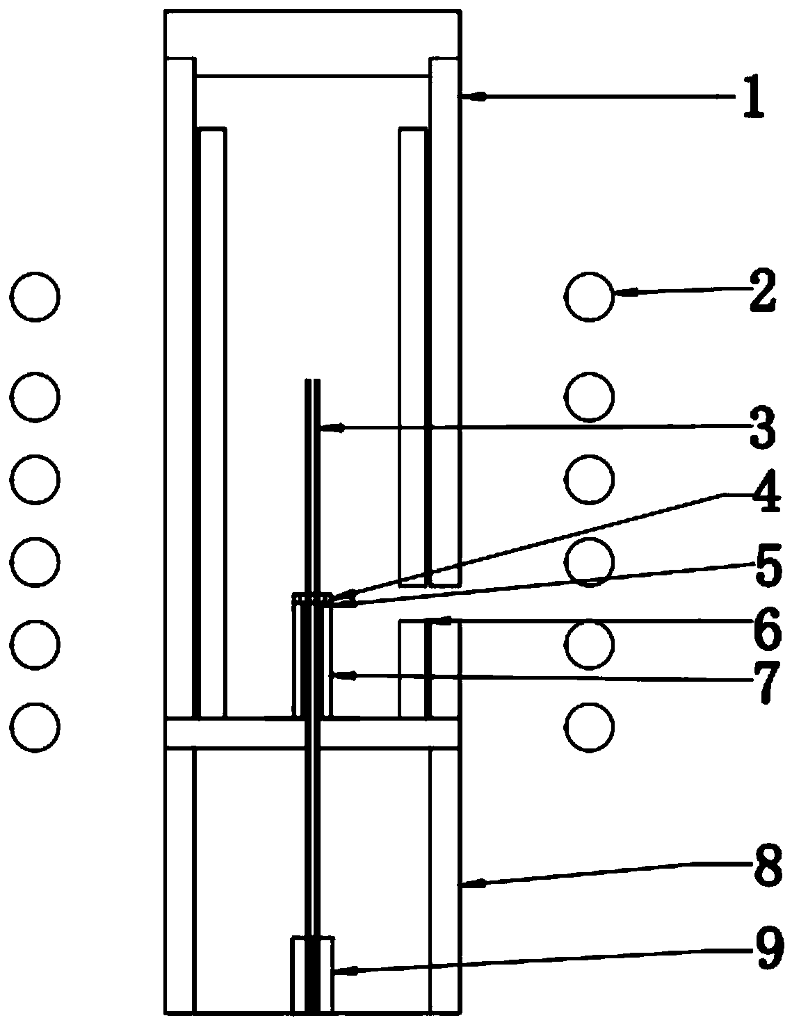
[0022] A micro-down-draw furnace device for high-power fiber laser fiber preparation adopts such as figure 1 The shown micro-drawing furnace device includes an insulation layer 1 arranged on the side wall of the furnace body, an induction coil 2 arranged outside the insulation layer 1, a quartz support column 8 arranged at the bottom of the furnace body, and a zirconia base 7 is arranged on the quartz support column 8, A heater 4 is arranged above the zirconia base 7, and a seed rod 9 is arranged inside the furnace body. The seed rod 9 is located inside the quartz support column 8 and placed at the bottom of the furnace body. The crystal optical fiber is inserted into the microporous crystal to form a prefabricated rod 3 through the heater 4, inserted into the seed rod 9. And the observation window 6 is set at the same height position of the zirconia base 7 and the insulation layer 1 . The zirconia base 7 is provided with an observation hole 5 whose cross-section is semicircu...

Embodiment 2

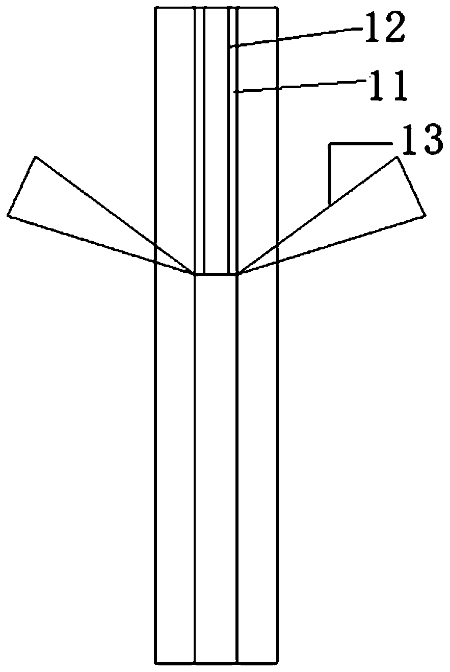
[0029] 1. First grow GGG crystal fiber 12 with a diameter of 0.3-1mm and a length of 60-180mm by micro-pull-down method, and then use the microporous crystal growth method mentioned in Patent No. 201410765560.6 to obtain a YAG microporous crystal 11 with a diameter of 0.32-1.02mm and a length of more than 180mm , process the outer circle of the microporous crystal to obtain a round tube with a rod, and finally plug the grown crystal fiber into the microporous crystal to form a preform 3;

[0030] 2. Put the optical fiber preform 3 obtained in the first step into figure 2 The laser heating furnace shown is fixed on the seed rod, and the thermal field is installed;

[0031] 3. After installing the thermal field, close the furnace door and evacuate to within 10Pa, fill in argon gas to 1.1 atmospheres, and start heating with the laser beam 13 until you can see that GGG starts to melt. Since the melting point of optical fiber GGG is 1800°C, the micropores in the outer layer The m...


PUM

PropertyMeasurementUnit
diameteraaaaaaaaaa
diameteraaaaaaaaaa
diameteraaaaaaaaaa

Abstract

The invention relates to an all-crystal optical fiber and a cladding making technology. The technology comprises the following steps of (1) using a micro-pull-down or guided-mode method, or a laser-heated pedestal method to obtain a crystal optical fiber with a diameter of 0.1 to 3 mm; (2) using a microporous crystal growth method to acquire a microporous crystal whose length is greater than or equal to an optical fiber length, or using a mechanical processing method to punch at the center of a crystal rod so as to acquire a crystal casing pipe with a micropore, wherein the core diameter of the casing pipe is slightly greater than the diameter of an optical fiber; and (3) inserting the crystal optical fiber acquired from the step1 into the microporous crystal or the crystal casing pipe acquired from the step2, melting parts of the crystal optical fiber in a micro-pull-down furnace or a laser-heated furnace, taking the crystal optical fiber as a raw material and a seed crystal, and thecrystal casing pipe as a crucible, and using the melted partial crystal optical fiber to crystallize on the surface of the unmelted crystal optical fiber so as to complete a whole crystal growth process. Compared with the prior art, by using the optical fiber and the technology of the invention, the seamless connection of a crystal core and a crystal cladding can be acquired, and uniform refractive index distribution is obtained so that a crystal optical fiber laser with high power can be acquired.

Description

technical field [0001] The invention belongs to the technical field of crystal material preparation, and relates to a manufacturing process of high-power fiber laser optical fiber and cladding. Background technique [0002] Silica fiber has made outstanding contributions in optical communication, and some people want to use it as a high-power laser to solve the problem of thermal effect faced by current high-power lasers. Thermal effect will lead to problems such as thermal depolarization and thermal-induced diffraction loss, which seriously affect the laser. The main performance indicators such as output power, conversion efficiency, and beam quality, and even damage to the gain medium in severe cases, are the most important limiting factors for the performance of high-power lasers. In order to alleviate the impact of thermal effects, technicians in related fields use gain media in the form of slabs, DISKs, and optical fibers to increase the surface area to volume ratio of ...

Claims


Application Information

Patent Timeline
Patent Type & Authority Patents(China)
IPC IPC(8): H01S3/067C30B15/34C30B15/08
CPCC30B15/08C30B15/34H01S3/06708
Inventor 徐军王东海李纳薛艳艳罗平王庆国唐慧丽
Owner TONGJI UNIV
Why Eureka
Try Eureka